EasyManua.ls Logo

Sony Trinitron KV-G21MW3 User Manual

Sony Trinitron KV-G21MW3
39 pages
To Next Page IconTo Next Page
Page #1 background imageLoading...
Page #1 background image
http://cxema.ru
MODEL COMMANDER DEST. CHASSIS NO.MODEL COMMANDER DEST. CHASSIS NO.
KV-G21MW3 RM-869 ME SCC-U07U-A
KV-G21QW3 RM-869 ME SCC-U07T-A
SERVICE MANUAL BG-2S
CHASSIS
TRINITRON
®
COLOR TV
Question and Answer IconNeed help?

Do you have a question about the Sony Trinitron KV-G21MW3 and is the answer not in the manual?

Sony Trinitron KV-G21MW3 Specifications

General IconGeneral
BrandSony
ModelTrinitron KV-G21MW3
CategoryTV
LanguageEnglish

Summary

Service Manual BG-2S Chassis

Model Identification

Lists TV models KV-G21MW3 and KV-G21QW3 with chassis.

Television Specifications

Detailed Specifications

Lists power, system, color, audio, inputs, outputs, and picture tube details.

Self Diagnosis Function

TV Operations Guide

Troubleshooting and Additional Information

Common Troubleshooting Issues

Addresses problems like no picture, no sound, snowy picture, and noisy sound.

Section 2 Disassembly Procedures

Picture Tube Removal

Anode Cap Handling and Removal

Provides instructions for safely removing and handling the picture tube anode cap.

Section 3 Set-Up Adjustments

Beam Landing Adjustment

Guides on adjusting beam landing using purity control and magnets.

Convergence Adjustments

Section 4 Circuit Adjustments

Service Mode Entry and Operations

Explains how to enter and navigate the service mode using the remote commander.

Operation Guide and Modifications

Service Mode and Data Management

Details NVM setup, service mode entry/exit, and data handling.

Board and Picture Adjustments

Memory Replacement Adjustments

Guides A board adjustment after IC003 replacement and data initialization.

Picture Distortion Adjustments

Details adjustments for horizontal and vertical picture distortions.

Circuit Board Locations

A Board Diagram and Components

Shows the physical layout and schematic of the A board.

Schematic Diagrams

C Board Diagram and Waveforms

Displays the schematic and critical waveforms for the C board.
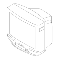
Section 7 Electrical Parts List

Related product manuals