EasyManua.ls Logo

Sony Trinitron KV-G21QW3 User Manual

Sony Trinitron KV-G21QW3
39 pages
To Next Page IconTo Next Page
Page #1 background imageLoading...
Page #1 background image
http://cxema.ru
MODEL COMMANDER DEST. CHASSIS NO.MODEL COMMANDER DEST. CHASSIS NO.
KV-G21MW3 RM-869 ME SCC-U07U-A
KV-G21QW3 RM-869 ME SCC-U07T-A
SERVICE MANUAL BG-2S
CHASSIS
TRINITRON
®
COLOR TV
Question and Answer IconNeed help?

Do you have a question about the Sony Trinitron KV-G21QW3 and is the answer not in the manual?

Sony Trinitron KV-G21QW3 Specifications

General IconGeneral
BrandSony
ModelTrinitron KV-G21QW3
CategoryTV
LanguageEnglish

Summary

Specifications

Power Requirements

Basic power input details.

Power Consumption

Power usage details.

Television System

Supported TV signal systems.

Color System

Supported color encoding systems.

Channel Coverage

Supported frequency bands.

Audio Output

Speaker output power.

Inputs and Outputs

Available input/output connectors.

Picture Tube and Screen Size

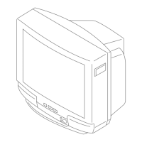
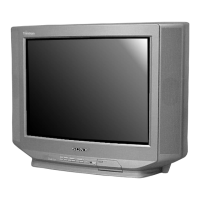
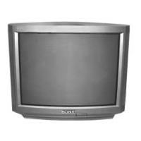
CRT tube and screen diagonal size.

Dimensions and Mass

Physical dimensions and unit weight.

Self Diagnosis Function

Device Identification

Components involved in self-diagnosis.

Flickering Frequency Codes

LED flicker codes for error indication.

Section 1 General

Connections and Equipment Setup

Connecting antennas and AV devices.

Channel Presetting

Quick Channel Presetting

Fast automatic channel tuning.

Automatic Channel Presetting

Automatic channel search and storage.

Manual Channel Presetting

Manual channel tuning and storage.

Disabling Program Positions

Removing unwanted preset channels.

TV Operations

Power Management

Procedures for powering TV on/off and standby.

Display and Sound Control

On-screen info, mute, and video input selection.

Timer and Language Settings

Scheduling operations and OSD language selection.

Troubleshooting Common Issues

Picture and Sound Problems

Resolving no picture, no sound, snowy picture.

Interference and Ghosting

Fixing signal interference and double images.

Minor Issues

Addressing noisy sound, stripes, or cabinet creaks.

Picture Adjustment Guide

Picture Mode Selection

Choosing preset picture styles.

Picture Setting Adjustments

Fine-tuning contrast, brightness, etc.

Section 2 Disassembly

Casing and Board Removal

Steps for removing rear cover and main board.

Part Replacement

Procedures for replacing internal components.

Section 2 Disassembly (Continuing)

Picture Tube and Anode Cap Removal

Safe procedures for CRT removal and anode cap handling.

Section 3 Set-Up Adjustments

Preparation and Beam Landing

Pre-adjustment steps and electron beam alignment.

Section 3 Set-Up Adjustments (Continuing)

Convergence Adjustments

Aligning color beams using magnets and yoke.

Section 3 Set-Up Adjustments (Continuing)

Dynamic and Corner Convergence

Adjusting convergence during scan and at screen edges.

Focus Adjustment

Adjusting picture sharpness.

Section 3 Set-Up Adjustments (Continuing)

Remote Commander Adjustments

Adjusting remote control functions.

White Balance and Screen Voltage

Calibrating color temperature and G2 voltage.

Section 4 Circuit Adjustments

Accessing Service Mode

Procedures to enter and navigate the service menu.

Section 4 Circuit Adjustments (Continuing)

Adjustment Method

Procedure for making service adjustments.

Adjustment Item Table

Adjustment Parameters (Items 00-41)

Detailed list of service adjustment parameters.

Option Notes

Data Value Notes

Explanation of standard data values.

Optional Feature Settings

Details on VPX, OP0, OP1, OP2 options.

Operation Guide

NVM Setup and Service Mode

Initializing memory and accessing service functions.

Board Adjustment Procedures

A Board Memory Replacement

Adjusting A board after memory IC replacement.

Picture Distortion Correction

Correcting geometric picture distortions.

Section 5 Diagrams

Block Diagram and Board Locations

System overview and circuit board layout.

Section 5 Diagrams (Continuing)

A Board Waveforms

Signal waveforms for the A board.

Section 5 Diagrams (Continuing)

A Board Schematics and PWB

Detailed circuit and PCB layouts for A board.

Section 5 Diagrams (Continuing)

C Board Schematics and PWB

Detailed circuit and PCB layouts for C board.

C Board Waveforms

Signal waveforms for the C board.

Semiconductor Components

Diodes and LEDs

Lists of diodes and light emitting diodes.

Transistors and ICs

Lists of transistors and integrated circuits.

Section 6 Exploded View and Parts

Chassis Exploded View

Diagram showing physical assembly of the chassis.

Key Part Identification

Major components like tubes, boards, and transformers.

Section 7 Electrical Parts List

Capacitors and Coils

Lists of capacitors and inductors.

Section 7 Electrical Parts List (Continuing)

Filters, Connectors, and Trimmers

Lists of filters, connectors, and trimmers.

Diodes and Transistors

Lists of diodes and transistors.

Section 7 Electrical Parts List (Continuing)

Integrated Circuits (ICs) and Jacks

Lists of ICs, jacks, and related components.

Other Components

Lists of fuses, ferrite beads, and coils.

Section 7 Electrical Parts List (Continuing)

Transistors

List of transistors by part number.

Resistors

List of resistors by part number.

Section 7 Electrical Parts List (Continuing)

Switches and Miscellaneous Parts

Lists of switches and other components.

Miscellaneous and Accessories

Accessories and Packing Materials

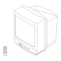
Included accessories and packaging details.

Remote Commander

Information specific to the remote control unit.

Related product manuals