Do you have a question about the Sony Trinitron KV-29DRC420 and is the answer not in the manual?
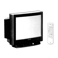
| Screen Size | 29 inches |
|---|---|
| Display Type | CRT |
| Aspect Ratio | 4:3 |
| Remote Control | Yes |
| Input Ports | Composite, S-Video, Component |
| Audio Output | Stereo |
Measures AC leakage from exposed metal parts to earth ground, limit 0.5 mA.
Procedure for identifying a reliable earth ground connection for leakage testing.
Defines how LED flashes indicate specific error causes and symptoms.
How to bring up and interpret error codes shown on the TV screen.
Procedure to reset diagnostic results to zero after repairs are completed.
Steps for removing the rear cover of the television.
Procedure for carefully detaching the chassis assembly from the bezel.
Instructions on how to position the unit for safe and effective servicing.
Safe procedure for removing the picture tube, emphasizing high voltage discharge.
Detailed steps and precautions for removing the anode cap from the picture tube.
Adjusts the convergence of red, green, and blue electron beams on the screen.
Adjusts vertical pin cushion and vertical centering for picture geometry.
Adjusts the alignment of red, green, and blue dots for precise image display.
Adjusts the sharpness and clarity of the picture by controlling electron beam focus.
Provides data for dynamic focus and quadrapole adjustments, crucial for focus across the screen.
Adjusts the screen grid voltage (G2) for proper picture brightness and contrast.
Covers adjustments for video input contrast, hue, and color settings.
Adjusts CRT white balance and sub bright for accurate color reproduction.
Steps to adjust color offset for white balance accuracy.
Adjusts the horizontal position of the raster on the screen for centering.
Corrects geometric distortions like trapezoid, pincushion, and line straightness.
Sets up the unit and checks input voltage before performing safety checks.
Verifies B+ voltage levels and HV output to ensure safe operation. Includes protector checks.
Checks the Ik protector circuit to ensure proper operation and prevent damage.
Confirms the hold-down function activates correctly, indicating proper power supply operation.
Procedures to restore the unit after service, including reconnecting wires and resetting settings.
Instructions for entering and navigating the service adjustment mode using the remote.
Procedure to retrieve and display data stored in the TV's memory.
Steps for modifying picture parameters using service mode adjustments.
Cautions and procedures for resetting NVM data, including deflection adjustments.
How to copy adjusted data (e.g., DF/DQP) between modes or memory locations.
Identifies and explains the function of remote control buttons used for service adjustments.
Provides default values and ranges for various circuit adjustments and settings.
Identifies the physical location and names of the main circuit boards within the TV.
Provides guidance on interpreting PWB layouts and schematic diagrams.
Illustrates the signal flow and interconnections between major functional blocks.
Contains detailed circuit diagrams and associated data for troubleshooting.
Explains symbols, abbreviations, and component notations used throughout the manual.
Illustrates the physical appearance and pinouts of various semiconductor components used in the TV.
Exploded view of the TV chassis, showing internal parts and their assembly.
Exploded view of the picture tube assembly, detailing its components.
Exploded view of the chassis for 30-inch and 34-inch models.
Exploded view of the picture tube assembly for 30 and 34-inch models.
Exploded view of the chassis for 32-inch and 36-inch models.
Exploded view of the picture tube assembly for 32 and 36-inch models.
Comprehensive list of all electrical components, including part numbers, descriptions, and values.
Explanations of component symbols, abbreviations, and notations used in the parts list.