EasyManua.ls Logo

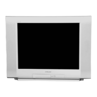
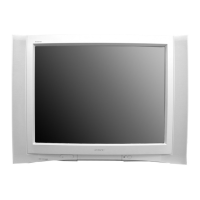
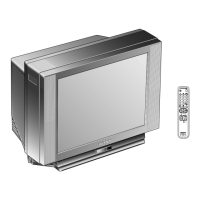
Sony Trinitron KV-29FS13 User Manual

Sony Trinitron KV-29FS13
123 pages
To Next Page IconTo Next Page
Page #1 background imageLoading...
Page #1 background image
TRINITRON
®
COLOR TELEVISION
SERVICE MANUAL
BA-5
CHASSIS
MODEL NAME REMOTE COMMANDER DESTINATION CHASSIS NO.
Self Diagnosis
Supported model
9-965-906-01
KV-29FS13
RM-Y180 E SCC-S56BA
KV-29FS13C
RM-Y180 E SCC-S38WA
KV-29FS13
RM-Y180

Table of Contents

Question and Answer IconNeed help?

Do you have a question about the Sony Trinitron KV-29FS13 and is the answer not in the manual?

Sony Trinitron KV-29FS13 Specifications

General IconGeneral
Screen Size29 inches
Display TechnologyCRT
Aspect Ratio4:3
Resolution480i
Speakers2
Sound OutputStereo
Audio Power Output2 x 10 W
Comb Filter3D comb filter
InputsS-Video

Summary

Specifications

Warnings and Cautions

Safety Check-Out

Self-Diagnostic Function

Self-Diagnostic Screen Display

How to view diagnostic results on screen.

Section 1: Disassembly

1-1. Rear Cover Removal

Procedure for removing the rear cover of the TV.

1-4. Picture Tube Removal

Detailed steps for removing the CRT picture tube.

Section 2: Set-Up Adjustments

2-1. Beam Landing

Procedure for aligning the electron beams for correct image display.

2-2. Convergence

Adjusting color convergence for a sharp image.

2-5. Method of Setting the Service Adjustment Mode

Guide to entering and operating the service adjustment mode.

2-6. White Balance Adjustments

Procedures for adjusting white balance for accurate colors.

Section 3: Safety Related Adjustments

3-1. R564 Confirmation Method (Hold-Down Confirmation) and Readjustments

Procedures for confirming and readjusting R564 for safety.

3-2. B+ Voltage Confirmation and Adjustment

Verifying and adjusting the B+ voltage for safe operation.

Section 4: Circuit Adjustments

4-1. Setting the Service Adjustment Mode

How to enter and set up the service adjustment mode.

4-4. MA Board Adjustments

Specific adjustments related to the MA board.

Section 5: Diagrams

5-1. Circuit Boards Location

Identifies the physical location of circuit boards.

5-3. Block Diagram

High-level overview of the TV's functional blocks.

A Board Schematic Diagram

Schematic for the A board.

5-4. Semiconductors

Lists and illustrates semiconductor components.

Section 6: Exploded Views

6-1. Chassis (KV-29FS13/29FS13C)

Exploded view of the TV chassis assembly.

6-2. Picture Tube Removal (KV-29FS13/29FS13C)

Exploded view detailing picture tube removal.

Section 7: Electrical Parts List

Related product manuals