— 21 —
KV-29FS13 / 29FS13C
4-4. MA BOARD ADJUSTMENTS
H. FREQUENCY (FREE RUN) CHECK
1. Input a TV mode (RF) with no signal.
2. Connect a frequency counter to base of Q501
(TP-500 H. DRIVE) on the A Board.
3. Check H. Frequency for 15735 ± 200 Hz.
V. FREQUENCY (FREE RUN) CHECK
1. Select video 1 with no signal input.
2. Set the conditions for a standard setting.
3. Connect the frequency counter to TP-508 (V OUT) or CN501 pin
6
(V DY+) and ground on the A Board .
4. Check that V. Frequency shows 60 ± 4 Hz.
DRIVE (RDRV)
1. Input a color-bar signal and set the level to 75%.
2. Set in Standard mode.
3. Activate the Service Adjustment Mode.
4. Set both GON and BON items. Using
3
and
6
set each to the
following values. Leave RON set to “1”.
service video rdrv
ntsc
vchp
Category
Display
Item
Mode
Item
Data
Signal
Type
00000000 00000000
26
R ON: ON (1)
G ON: OFF (0)
B ON: OFF (0)
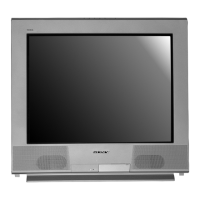
5. Connect an oscilloscope probe to CB Board, J701 Pin 12 (KR) (Red
Out) .
6. Select RDRV with
1
and
4
.
7. Adjust the value of RDRV with
3
and
6
for
92.5 ± 3 VDC.
92.5 ± 3VDC
8. Reset GON and BON values to “1”.
R ON: ON (1)
G ON: ON (1)
B ON: ON (1)
9. Press
MUTING
then
ENTER
to save into the memory.
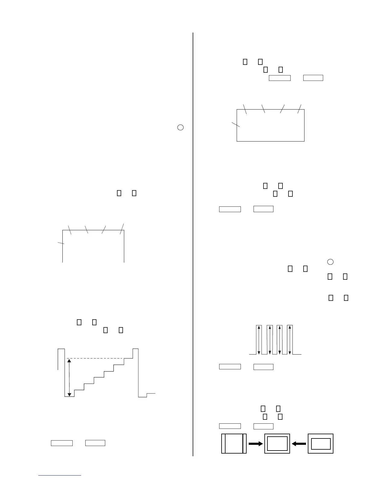
DISPLAY POSITION ADJUSTMENT (DISP)
1. Input a color-bar signal.
2. Set to Service Adjustment Mode.
3. Select DISP with
1
and
4
.
4. Adjust values of DISP with
3
and
6
to adjust characters to the center.
5. Write to memory by pressing
MUTING
then
ENTER
.
6. Check to see if the text is displayed on the screen.
service micro disp 48
ntsc
vchp
Category
Display
Item
Mode
Item
Data
Signal
Type
00000000 00000000
SUB BRIGHT ADJUSTMENT (SBRT)
1. Input a monoscope signal.
2. Activate the Service Adjustment Mode.
3. Set the PICTURE and BRIGHTNESS to minimum.
4. Select the SBRT item with
1
and
4
.
5. Adjust the values of SBRT with
3
and
6
to obtain a faintly visible
crosshatch.
6. Press
MUTING
then
ENTER
to save into the memory.
SUB HUE, SUB COLOR ADJUSTMENT
(SHUE, SCOL)
1. Input a color-bar signal.
2. Activate the Service Adjustment Mode.
3. Connect an oscilloscope probe to CA Board, CN705 Pin
4
Blue Out.
4. Select the SHUE and SCOL item with
1
and
4
.
5. While showing the SHUE item, adjust the waveform with
1
and
4
until the second and third bars show the same level (V2 = V3 < 0.1
Vp-p).
6. While showing the SCOL item, adjust the waveform with
3
and
6
until the fi rst and fourth bars show the same level (V1 = V4 < 0.1
Vp-p).
V1
V2 V3
V4
7. Press
MUTING
then
ENTER
to save into the memory.
V. SIZE ADJUSTMENT (VSIZ)
1. Input a crosshatch signal.
2. Activate the Service Adjustment Mode.
3. Select the VSIZ item with
1
and
4
.
4. Adjust value of VPOS with
1
and
4
for the best vertical center.
5. Press
MUTING
then
ENTER
to save into the memory.