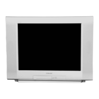
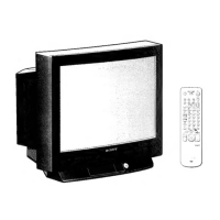
Do you have a question about the Sony TRINITRON KV-29FS100 and is the answer not in the manual?
Procedures for testing AC leakage current from exposed metal parts to earth ground.
Method for identifying a reliable earth ground connection for safety tests.
Explains STANDBY/TIMER LED flash counts indicating probable causes of errors.
Visual representation of STANDBY/TIMER LED flash counts and corresponding diagnostic items.
Instructions on how to turn off the STANDBY/TIMER LED flash.
How to display past error occurrences on the screen for confirmation.
Guidance on checking and clearing self-diagnostic screen results.
Steps to clear the self-diagnostic result display to "0".
How to exit the self-diagnostic screen.
Procedure for removing the rear cover of the TV.
Steps to remove the main chassis assembly from the TV.
How to position the TV for servicing.
Instructions for safely removing the picture tube from the TV.
Specific steps for removing the anode cap from the picture tube.
Guidelines on safely handling the picture tube anode cap.
Adjusting beam landing for proper picture alignment.
Adjusting color convergence for sharpness and clarity.
Static adjustments for vertical and horizontal convergence.
Using the BMC magnet for convergence adjustment.
Adjusting the Y separation axis correction magnet.
Dynamic adjustments for picture convergence.
Adjusting convergence in the screen corners.
Adjusting the TLH plate for horizontal convergence.
Adjusting the picture focus for sharpness.
Adjusting screen grid (G2) voltage for brightness.
Adjusting white balance for accurate color reproduction.
Confirmation and readjustment of R530/R531 for safety.
Confirming and adjusting B+ voltage for safety.
Steps to enter the service adjustment mode using the remote.
Procedure to confirm memory write after adjustments.
Overview of remote control buttons used for adjustments.
Reference list of NVM data parameters for service adjustments.
Table mapping model and destination to ID variations.
Adjustments specific to the A Board.
Checking the horizontal frequency in free run mode.
Checking the vertical frequency in free run mode.
Adjusting sub-contrast (RDRV) for picture color.
Adjusting display position for centering text.
Adjusting sub-bright for picture display.
Adjusting sub-hue and sub-color for picture tone.
Adjusting vertical picture size.
Adjusting vertical picture centering.
Adjusting horizontal picture centering.
Adjusting horizontal picture size.
Adjusting linearity, correction, pin amp, and trapezoid distortion.
Adjusting vertical angle, bow, and pin distortion.
Saving service adjustments to memory.
Diagram showing the location of various circuit boards.
Information on interpreting PWB diagrams and schematic symbols.
High-level block diagrams and detailed schematics.
Schematic diagram for the A Board.
Schematic diagram for the HS Board.
Schematic diagram for the HU Board.
Schematic diagram for the C Board.
Schematic diagram for the GK Board.
Schematic diagram for the P Board.
Schematic diagram for the HR Board.
Schematic diagram for the S Board.
Schematic diagram for the V Board.
Schematic diagram for the HZ Board.
Illustrations and part numbers for semiconductor devices.
Exploded view of the chassis for specific models.
Exploded view of the picture tube for specific models.
Exploded view of the chassis for specific models.
Exploded view of the picture tube for specific models.



 Loading...