EasyManua.ls Logo

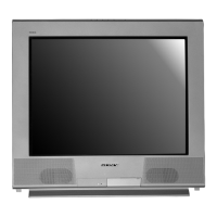
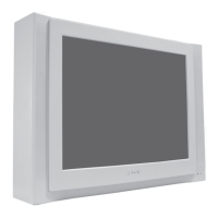
Sony Trinitron KV-29FS120 User Manual

Sony Trinitron KV-29FS120
120 pages
To Next Page IconTo Next Page
Page #1 background imageLoading...
Page #1 background image
TRINITRON
®
COLOR TELEVISION
SERVICE MANUAL
BA-6
CHASSIS
MODEL NAME REMOTE COMMANDER DESTINATION CHASSIS NO.
9-965-960-01
KV-27FS120
RM-Y195 US SCC-S61N-A
KV-27FS120
RM-Y195 CANADA SCC-S59J-A
KV-29FA310
RM-Y180 LATIN NORTH SCC-S60V-A
KV-29FA310
RM-Y180 LATIN SOUTH SCC-S60W-A
KV-29FS120
RM-Y195 LATIN NORTH SCC-S73D-A
KV-29FS120
RM-Y195 LATIN SOUTH SCC-S73E-A
HISTORY INFORMATION FOR THE FOLLOWING MANUAL:
ORIGINAL MANUAL ISSUE DATE: 3/2004
REVISION DATE SUBJECT
3/2004 No revisions or updates are applicable at this time.

Table of Contents

Questions and Answers:

Sony Trinitron KV-29FS120 Specifications

General IconGeneral
Screen Size29 inches
Display TechnologyCRT
Aspect Ratio4:3
Resolution480i
Weight43 kg
Comb Filter3D Digital Comb Filter
Speakers2
InputsComposite, S-Video

Summary

Specifications

Warnings and Cautions

CAUTION

General caution about electrical hazards and opening the unit.

WARNING!!

Warning about using an isolation transformer due to live chassis.

SAFETY-RELATED COMPONENT WARNING!!

Warning about critical safety components identified in diagrams.

Safety Check-Out

Leakage Test

Procedures for checking AC leakage current from exposed metal parts.

How to Find a Good Earth Ground

Methods to identify a reliable earth ground connection for safety tests.

Self-Diagnostic Function

Diagnostic Test Indicators

Explanation of STANDBY/TIMER LED flash codes indicating potential problems.

Display of Standby/Timer LED Flash Count

Table detailing diagnostic items and their corresponding LED flash counts.

SECTION 1: DISASSEMBLY

1-1. Rear Cover Removal (All Except KV-29FA310)

Steps to remove the rear cover for models other than KV-29FA310.

1-2. Rear Cover Removal (KV-29FA310 Only)

Steps to remove the rear cover specifically for the KV-29FA310 model.

1-3. Chassis Assembly Removal (All Except KV-29FA310)

Procedure for removing the chassis assembly from non-KV-29FA310 models.

1-4. Chassis Assembly Removal (KV-29FA310 Only)

Procedure for removing the chassis assembly from the KV-29FA310 model.

1-5. Service Position (All Except KV-29FA310)

Steps to place the unit in a service position for non-KV-29FA310 models.

1-6. Service Position (KV-29FA310 Only)

Steps to place the unit in a service position for the KV-29FA310 model.

1-7. Picture Tube Removal

Detailed steps for removing the picture tube, including safety precautions.

SECTION 2: SET-UP ADJUSTMENTS

2-1. Beam Landing

Procedure for adjusting beam landing for proper color convergence.

2-2. Convergence

Instructions for static and horizontal convergence adjustments.

2-3. Focus

Procedure for adjusting the focus control for optimal picture clarity.

2-4. Screen (G2)

Steps for adjusting the screen grid voltage for proper brightness.

2-5. Method of Setting the Service Adjustment Mode

Guide on how to enter and navigate the service adjustment mode.

2-6. White Balance Adjustments

Procedure for adjusting white balance for accurate color reproduction.

SECTION 3: SAFETY RELATED ADJUSTMENTS

3-1. R564 Confirmation Method (HV Hold-Down Confirmation) and Readjustments

Procedure to confirm and readjust R564 for HV hold-down safety.

3-2. B+ Voltage Confirmation and Adjustment

Steps to confirm and adjust the B+ voltage on the A Board.

SECTION 4: CIRCUIT ADJUSTMENTS

4-1. Setting the Service Adjustment Mode

How to enter the service adjustment mode using the remote control.

4-2. Memory Write Confirmation Method

Procedure to confirm that adjustments have been saved to memory.

4-3. Remote Adjustment Buttons and Indicators

Overview of remote control buttons used for service adjustments.

4-4. Service Data Lists

Comprehensive list of service data parameters and their initial values.

4-5. A Board Adjustments

Adjustments related to the A board, including frequency checks and display settings.

SECTION 5: DIAGRAMS

5-1. Circuit Boards Location

Diagram showing the location of various circuit boards within the TV.

5-3. Block Diagram and Schematics

Overall system block diagram and schematic references.

SECTION 6: EXPLODED VIEWS

6-1. Picture Tube (KV-27FS120/29FS120 Only)

Exploded view diagram of the picture tube assembly for specific models.

6-2. Chassis (KV-27FS120/29FS120 Only)

Exploded view diagram of the chassis components for specific models.

6-3. Picture Tube (KV-29FA310 Only)

Exploded view diagram of the picture tube assembly for the KV-29FA310 model.

6-4. Chassis (KV-29FA310 Only)

Exploded view diagram of the chassis components for the KV-29FA310 model.

SECTION 7: ELECTRICAL PARTS LIST

Operating Instructions

Connecting Additional Equipment

Guide on connecting external devices to the television.

IMPORTANT SAFEGUARDS

Use

Basic safety precautions regarding the use of the television.

Ventilation

Importance of not blocking ventilation openings to prevent overheating.

Object and Liquid Entry

Warnings about inserting objects or liquids into the TV.

IMPORTANT SAFEGUARDS

Servicing

Advice against self-servicing due to electrical hazards.

Damage Requiring Service

Specific conditions that necessitate unplugging and referring to service.

Connections

Connecting Your TV

Basic instructions for setting up TV connections.

Cable Box Connections

TV and Cable Box

Instructions for connecting a cable box to the TV for viewing channels.

Connecting Additional Equipment

Connecting a TV and VCR

Steps for connecting a VCR to the TV for playback and recording.

Optional connection

Advice on using S-Video or Audio/Video cables for better picture quality.

Using your TV with this connection

How to program the remote and switch inputs for VCR connectivity.

Connecting a TV, VCR, Cable/Antenna, and Satellite Receiver using Composite Video (VIDEO/AUDIO L(MONO), R)

Using your TV with this connection

Guide for connecting multiple devices using composite video connections.

Connecting a DVD Player using Composite Video (VIDEO/AUDIO L(MONO),R)

Optional connection

Using S-Video for better picture quality with DVD players.

Connecting a DVD Player using Component Video (Y, PB, PR/R, L)

Using your TV with this connection

Steps to connect a DVD player using component video for improved picture.

Connecting an Audio System

Connecting a Camcorder (for playback)

How to connect a camcorder for video playback.

Connecting for Video Tape Editing (VCR and Camcorder)

Using your TV with this connection

Steps for connecting VCRs and camcorders for video editing.

Troubleshooting

General

Common TV problems and their solutions.

Control Remote

Troubleshooting issues related to the remote control.

Video

No picture, no sound

Troubleshooting steps for issues with picture and sound.

Dotted lines or stripes

How to fix horizontal lines or stripes on the screen.

Audio

Good picture, no sound

Troubleshooting steps for audio issues when the picture is fine.

Channels

Contacting Sony

Information on how to contact Sony customer support for assistance.

IMPORTANT SAFEGUARDS

Use

Basic safety precautions regarding the use of the television.

Ventilation

Importance of not blocking ventilation openings to prevent overheating.

Object and Liquid Entry

Warnings about inserting objects or liquids into the TV.

IMPORTANT SAFEGUARDS

Servicing

Advice against self-servicing due to electrical hazards.

Damage Requiring Service

Specific conditions that necessitate unplugging and referring to service.

Connecting Your TV

TV Rear Panel

Diagram and labels for the TV's rear connection panel.

Basic Connections

TV with Cable, Indoor, or Outdoor Antenna

Guide for connecting antennas or cable systems to the TV.

Troubleshooting

General

Common TV problems and their solutions.

Control Remote

Troubleshooting issues related to the remote control.

Control Remote

Programming the Remote Control

Instructions for programming the remote control for various functions.

Related product manuals