Do you have a question about the Sony TRINITRON KV-HA21P50 and is the answer not in the manual?
Initial release of the manual or product.
Modification in the rear cover assembly suffix.
Indicates error causes and symptoms through lamp flashes and screen displays.
Explains how to interpret the flashing pattern of the standby/timer lamp.
Procedure to stop the flashing standby/timer lamp.
How to view stored failure data on the screen.
Clearing diagnostic results and quitting the self-diagnostic screen.
Diagram and explanation of the self-diagnostic circuit components.
Step-by-step instructions for initial setup and connection.
Essential safety warnings for operating the TV and handling components.
Instructions on how to secure the TV to prevent tipping.
Diagrams identifying front and rear panel controls and connectors.
Guide for connecting external video and audio systems.
Instructions for connecting to the monitor output terminal.
Common TV problems with their corresponding solutions.
Procedure to set the TV's wake up and sleep timers.
Steps for automatically scanning and storing TV channels.
Steps for manually tuning and storing desired TV channels.
How to choose different picture modes for viewing.
How to choose different sound modes for listening.
Guide to adjusting picture and sound parameters.
How to correct picture slant using the PIC ROTATION function.
Instructions for removing the rear cover of the TV.
Steps to remove the speaker assembly from the TV.
Procedure for removing the main chassis assembly.
How to place the TV in a service-friendly position.
Instructions for removing the terminal board bracket.
Procedures for replacing common TV components.
Detailed steps for safely removing the picture tube.
Procedure for removing and safely handling the anode cap.
Procedure to align the electron beam for proper picture display.
Procedure to align the RGB colors for sharp images.
Using BMC magnet to balance and align RGB dots.
Adjusting convergence dynamically for screen corners.
Correcting screen-corner misconvergence using permalloy.
Procedure to achieve the sharpest focus for the picture.
Procedure to set accurate white balance for correct colors.
Adjusting sub brightness for optimal picture contrast.
Procedure to adjust the G2 (screen) voltage for proper picture cut-off.
Procedures for performing service adjustments using the remote commander.
General method for adjusting service items and writing data.
Procedure for saving adjusted settings into the TV's memory.
How to confirm that adjustments have been successfully saved.
How to exit the service mode and return to normal TV operation.
Overview of other functions available through the remote commander.
Adjusting sub color parameters for optimal color reproduction.
Adjusting sub hue parameters for correct color tint.
Deflection adjustments for the 50Hz TV system.
Deflection adjustments for the 60Hz TV system.
Steps for adjusting the A board after replacing the memory IC.
Adjustments for horizontal and vertical picture distortions.
Overall functional block diagram of the TV's internal circuitry.
Diagrams showing the physical location of major circuit boards.
Detailed circuit schematic diagrams for the TV's components.
Schematic diagram for the CV board.
List of expected voltage measurements for components on the A board.
List of expected voltage measurements for components on the CV board.
Reference waveforms for troubleshooting the A board.
Reference waveforms for troubleshooting the CV board.
Diagram showing component placement on the CV board.
Diagram showing component placement on the A board.
Illustrations and part numbers for various diodes.
Illustrations and part numbers for various transistors.
Illustrations and part numbers for various integrated circuits.
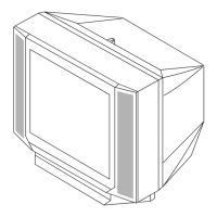
Exploded view diagram of the picture tube and chassis assembly.
List of capacitors with part numbers, descriptions, and remarks.
List of connectors with part numbers and descriptions.
List of diodes with part numbers and descriptions.
List of integrated circuits with part numbers and descriptions.
List of transistors with part numbers and descriptions.
List of resistors with part numbers and descriptions.
List of coils with part numbers and descriptions.
List of variable resistors with part numbers and descriptions.
List of included accessories, packing materials, and manuals.
Accessories and packing materials specific to the CV board.
Reference to exploded view of picture tube and chassis from main manual.
| Screen Size | 21 inches |
|---|---|
| Display Type | CRT |
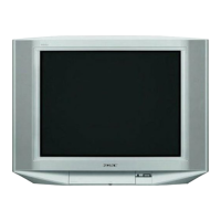
| Brand | Sony |
| Aspect Ratio | 4:3 |
| Tuner | Analog |
| Inputs | Composite |