Do you have a question about the Sony TRINITRON KV-HA21M80 and is the answer not in the manual?
Lists models, commanders, and chassis numbers for the BG2T chassis.
Details power, TV system, color system, channels, audio, and dimensions.
Explains STANDBY/TIMER lamp flash codes for error diagnosis.
Instructions on how to view diagnostic results on the screen.
Step-by-step guide for initial TV setup and operation.
Critical safety warnings about electrical hazards and installation.
Lists common TV problems and their corresponding solutions.
Explains the function of each button on the remote control.
Procedures for setting wake up/sleep timers and presetting channels.
Selecting picture/sound modes and adjusting settings.
Steps for removing rear cover, chassis, and picture tube.
Guidance for replacing components like light guides and power buttons.
Steps for beam landing, convergence, focus, and white balance.
Performing service adjustments using the remote commander.
Steps to enter, exit, and operate the service mode.
Overall system block diagram and detailed schematic diagrams.
Waveform examples from A and CV boards for diagnostic reference.
List of components (capacitors, transistors, resistors) on the A board.
List of components on the CV board (connectors, coils, etc.).
List of voltage measurements for A and CV boards.
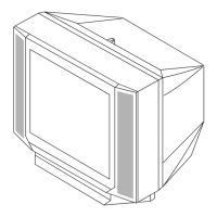
Exploded view of the picture tube and chassis assembly.
List of parts for the picture tube and chassis assembly.
List of capacitors with part numbers and specifications.
List of transistors and resistors with part numbers and specifications.
Reference to exploded view for rear cover Assy change.