EasyManua.ls Logo

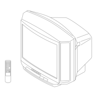
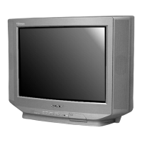
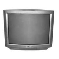
Sony TRINITRON KV-J25MF8J User Manual

Sony TRINITRON KV-J25MF8J
52 pages
To Next Page IconTo Next Page
Page #1 background imageLoading...
Page #1 background image
MODEL COMMANDER DEST. CHASSIS NO.
KV-J25MF8J
RM-873 ME SCC-K57P-A
MODEL COMMANDER DEST. CHASSIS NO.
KV-J29MF8J
RM-873 ME SCC-K57N-A
CHASSIS
TRINITRON
®
COLOR TV
BG-1L
SERVICE MANUAL
Question and Answer IconNeed help?

Do you have a question about the Sony TRINITRON KV-J25MF8J and is the answer not in the manual?

Sony TRINITRON KV-J25MF8J Specifications

General IconGeneral
Display TypeCRT
Aspect Ratio4:3
BrandSony
ModelKV-J25MF8J
Screen Size25 inches
Input PortsComposite

Summary

Specifications

Section 1 General

Connections

Explains antenna and external equipment connection.

Section 1 General Continued

Introducing the Menus

Explains on-screen menu navigation and features.

Changing the Menu Language

Steps to change the TV menu language.

Section 1 General Continued

Presetting Channels

Details automatic and manual channel presetting procedures.

Section 1 Operations

Watching the TV

Covers basic TV operation like power, channel, volume, and mute.

Setting the Wake Up Timer

How to schedule the TV to turn on automatically.

Section 1 Operations Continued

Setting the Sleep Timer

How to schedule the TV to turn off automatically.

Adjusting the Picture and Sound

Selecting picture/sound modes and adjusting settings.

Section 1 Operations Continued

Listening to the Surround Sound

Explains surround sound feature and its settings.

Section 1 Operations Continued

Customizing the TV

Adjusting AV OUT and picture tilt for TV customization.

Section 2 Disassembly

2-1. Rear Cover Removal

Procedure for removing the TV's rear cover.

2-2. Speaker Removal

Procedure for removing the TV speaker.

2-3. Chassis Assy Removal

Procedure for removing the TV chassis assembly.

Section 2 Disassembly Continued

2-4. Service Position

How to place the TV in a service position.

2-5. S1 Board Removal

Procedure for removing the S1 circuit board.

2-6. A and D Boards Removal

Procedure for removing the A and D circuit boards.

Section 2 Disassembly Continued

2-7. F1 and H3 Boards Removal

Procedure for removing F1 and H3 circuit boards.

2-8. Picture Tube Removal

Procedure for removing the TV's picture tube.

Section 2 Disassembly Continued

Anode-Cap Removal

Safety notes and procedure for removing the anode cap.

Section 3 Set-Up Adjustments

3-1. Beam Landing

Adjusting beam landing using pattern generator and magnets.

Section 3 Set-Up Adjustments Continued

3-2. Convergence

Adjusting static convergence using magnets and controls.

Section 3 Set-Up Adjustments Continued

BMC (Hexapole) Magnet Operation

Using BMC magnet for color dot alignment.

Section 3 Set-Up Adjustments Continued

Dynamic Convergence Adjustment

Adjusting dynamic convergence by moving the deflection yoke.

Screen-corner Convergence

Affixing Permalloy for screen-corner convergence.

Section 3 Set-Up Adjustments Continued

3-3. Focus Adjustment

Adjusting the focus control on the flyback transformer.

Memory Write Confirmation

Method to confirm memory write after adjustment.

Section 3 Set-Up Adjustments Continued

3-4. G2 (Screen) and White Balance Adjustments

Procedures for G2 and White Balance adjustments.

Sub Bright Adjustment

Adjusting sub-bright for optimal stripe visibility.

Section 4 Self Diagnosis Function

Section 5 Circuit Adjustments

5-1. Adjustments with Commander

Entering service mode and using the RM-871 commander.

Section 5 Circuit Adjustments Continued

5-2. Adjustment Method

Explanation of adjustment procedures using buttons and screen display.

Section 5 Circuit Adjustments Continued

Adjustment Item Table

Table listing adjustment items, data ranges, and standard data.

Section 5 Circuit Adjustments Continued

Adjustment Item Table (continued)

Continues the list of adjustment items and related data.

Section 5 Circuit Adjustments Continued

Adjustment Item Table (continued)

Continues the list of adjustment items and related data.

Section 5 Circuit Adjustments Continued

Picture Quality Adjustments

Adjustments for Sub-Hue, Sub-Contrast, and Sub-Color.

A Board Adjustment

Procedures for adjusting specific items on the A board.

A Board Adjustment After IC003 Replacement

Steps for adjusting A board after IC003 replacement.

Picture Distortion Adjustment

Adjustments for picture distortion items.

Section 6 Diagrams

Block Diagram

Overall block diagram of the TV system.

Section 6 Diagrams Continued

Frame Schematic Diagram

Schematic diagram for the main frame of the TV.

Circuit Boards Location

Diagram showing the physical location of various circuit boards.

Section 6 Diagrams Continued

Schematic Diagram of VM Board

Detailed schematic diagram of the VM Board.

Section 6 Diagrams Continued

D Board

Schematic and component list for the D Board.

F1 Board

Schematic and component list for the F1 Board.

H3 Board

Schematic and component list for the H3 Board.

Section 6 Diagrams Continued

Schematic Diagrams of D, F1 and Hs Boards

Combined schematic diagrams for D, F1, and H3 boards.

Section 6 Diagrams Continued

Schematic Diagrams of A Board

Detailed schematic diagram of the A Board.

Section 6 Diagrams Continued

A Board Waveforms

Waveforms for various signals on the A Board.

A Board

Component layout diagram for the A Board.

Section 6 Diagrams Continued

Schematic Diagram of S1 Board

Detailed schematic diagram of the S1 Board.

Section 6 Diagrams Continued

Schematic Diagram of C2 Board

Detailed schematic diagram of the C2 Board.

Section 6 Diagrams Continued

Semiconductors

List and images of various semiconductor components used.

Section 7 Exploded Views

Picture Tube

Exploded view and parts list for the picture tube assembly.

Section 7 Exploded Views Continued

Chassis

Exploded view and parts list for the chassis assembly.

Section 8 Electrical Parts List

F1 and A Board Parts

Electrical parts list for F1 and A boards, including capacitors and connectors.

Section 8 Electrical Parts List Continued

Capacitors

List of capacitors for various boards.

Section 8 Electrical Parts List Continued

IC, Jacks, Transistors, Resistors, Switches

List of ICs, Jacks, Transistors, Resistors, and Switches.

Section 8 Electrical Parts List Continued

Resistors (R001-R155)

List of resistors (R001-R155).

Section 8 Electrical Parts List Continued

Resistors (R156-R801)

List of resistors (R156-R801).

Section 8 Electrical Parts List Continued

Resistors (R804-R1551)

List of resistors (R804-R1551).

Section 8 Electrical Parts List Continued

Resistors (R1801-R2608)

List of resistors (R1801-R2608).

Section 8 Electrical Parts List Continued

Resistors (R2523-R2612)

List of resistors (R2523-R2612).

Section 8 Electrical Parts List Continued

Diodes, Transistors, Resistors

List of diodes, transistors, and resistors for specific boards.

Section 8 Electrical Parts List Continued

Resistors (R611-R1800)

List of resistors (R611-R1800).

Section 8 Electrical Parts List Continued

Resistors (R2523-R2612)

List of resistors (R2523-R2612).

Section 8 Electrical Parts List Continued

S1 Board Components

List of Capacitors, ICs, Chip Conductors, Transistors, Resistors for S1 Board.

Section 8 Electrical Parts List Continued

Miscellaneous, Accessories, Remote Commander

Lists miscellaneous parts, accessories, packing materials, and remote commander.

Related product manuals