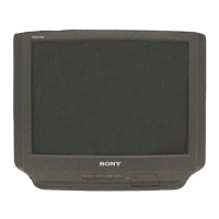
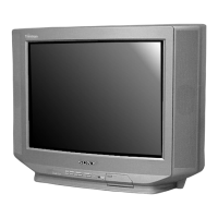
Do you have a question about the Sony TRINITRON KV-J25MF8J and is the answer not in the manual?
| Display Type | CRT |
|---|---|
| Aspect Ratio | 4:3 |
| Brand | Sony |
| Model | KV-J25MF8J |
| Screen Size | 25 inches |
| Input Ports | Composite |
Explains antenna and external equipment connection.
Explains on-screen menu navigation and features.
Steps to change the TV menu language.
Details automatic and manual channel presetting procedures.
Covers basic TV operation like power, channel, volume, and mute.
How to schedule the TV to turn on automatically.
How to schedule the TV to turn off automatically.
Selecting picture/sound modes and adjusting settings.
Explains surround sound feature and its settings.
Adjusting AV OUT and picture tilt for TV customization.
Procedure for removing the TV's rear cover.
Procedure for removing the TV speaker.
Procedure for removing the TV chassis assembly.
How to place the TV in a service position.
Procedure for removing the S1 circuit board.
Procedure for removing the A and D circuit boards.
Procedure for removing F1 and H3 circuit boards.
Procedure for removing the TV's picture tube.
Safety notes and procedure for removing the anode cap.
Adjusting beam landing using pattern generator and magnets.
Adjusting static convergence using magnets and controls.
Using BMC magnet for color dot alignment.
Adjusting dynamic convergence by moving the deflection yoke.
Affixing Permalloy for screen-corner convergence.
Adjusting the focus control on the flyback transformer.
Method to confirm memory write after adjustment.
Procedures for G2 and White Balance adjustments.
Adjusting sub-bright for optimal stripe visibility.
Entering service mode and using the RM-871 commander.
Explanation of adjustment procedures using buttons and screen display.
Table listing adjustment items, data ranges, and standard data.
Continues the list of adjustment items and related data.
Continues the list of adjustment items and related data.
Adjustments for Sub-Hue, Sub-Contrast, and Sub-Color.
Procedures for adjusting specific items on the A board.
Steps for adjusting A board after IC003 replacement.
Adjustments for picture distortion items.
Overall block diagram of the TV system.
Schematic diagram for the main frame of the TV.
Diagram showing the physical location of various circuit boards.
Detailed schematic diagram of the VM Board.
Schematic and component list for the D Board.
Schematic and component list for the F1 Board.
Schematic and component list for the H3 Board.
Combined schematic diagrams for D, F1, and H3 boards.
Detailed schematic diagram of the A Board.
Waveforms for various signals on the A Board.
Component layout diagram for the A Board.
Detailed schematic diagram of the S1 Board.
Detailed schematic diagram of the C2 Board.
List and images of various semiconductor components used.
Exploded view and parts list for the picture tube assembly.
Exploded view and parts list for the chassis assembly.
Electrical parts list for F1 and A boards, including capacitors and connectors.
List of capacitors for various boards.
List of ICs, Jacks, Transistors, Resistors, and Switches.
List of resistors (R001-R155).
List of resistors (R156-R801).
List of resistors (R804-R1551).
List of resistors (R1801-R2608).
List of resistors (R2523-R2612).
List of diodes, transistors, and resistors for specific boards.
List of resistors (R611-R1800).
List of resistors (R2523-R2612).
List of Capacitors, ICs, Chip Conductors, Transistors, Resistors for S1 Board.
Lists miscellaneous parts, accessories, packing materials, and remote commander.