Do you have a question about the Sony Trinitron KV-TG21M61 and is the answer not in the manual?
Basic setup procedures for the TV and remote.
Important safety warnings regarding high voltages and handling.
Instructions on how to physically secure the TV for safety.
Identification of TV controls and connection terminals.
Procedure for removing the rear cover of the TV.
Steps for detaching the speakers from the TV chassis.
Guide to removing the main chassis assembly.
Instructions for removing the F board.
How to place the TV in a service-friendly position.
Steps for removing the terminal bracket.
Procedure for removing A3 and V2 boards.
General guidance for replacing specific parts like light guides.
Detailed instructions for removing the picture tube.
Adjusting beam landing for proper picture geometry.
Aligning red, green, and blue electron beams for accurate color.
Adjusting the focus control for a sharp picture.
Adjusting screen voltage and white balance for optimal picture quality.
How to enter service mode and perform adjustments using the remote.
General procedure for making specific circuit adjustments.
Fine-tuning picture quality settings like color and hue.
Adjusting deflection parameters for image geometry.
Specific adjustments for the A board after memory IC replacement.
Correcting various forms of picture distortion.
Overall functional block diagram of the TV system.
Visual guide to the location of various circuit boards.
Detailed electronic schematic diagrams for the TV.
Lists expected voltage readings at various test points for troubleshooting.
Displays expected signal waveforms at key test points.
Visual layout of components on printed wiring boards.
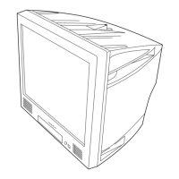
Exploded view showing the main components of the TV chassis.
Comprehensive list of all electrical components and their part numbers.