Do you have a question about the Sony Trinitron PVM-1340 and is the answer not in the manual?
Section for recording model and serial numbers for product registration and dealer reference.
Crucial safety instructions regarding fire and electric shock hazards, and general warnings.
Guidelines for safe operation, installation, cleaning, and repacking the unit.
A detailed chart comparing the features available across different monitor models.
Explanations of specific features like picture tubes, input connectors, and special operating modes.
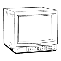
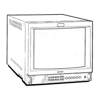
Diagrams and numbering of controls on the front panels for various PVM models.
In-depth explanations for each front panel button, control, and indicator.
Specific description of controls for the PVM-1340 model's front panel.
Diagrams and numbering of connectors and controls on the rear panels for various PVM models.
Comprehensive explanations of the function and connection for each rear panel connector.
Detailed descriptions of digital and analog RGB connector pin assignments and usage.
A table detailing which picture adjustment buttons are operational in different input modes.
Technical details on frequency response, band pass, picture linearity, and convergence.
Specifications for audio output, CRT type, power consumption, dimensions, and weight.
Pin assignments for the 9-pin DIGITAL RGB connector, detailing signal types and levels.
Pin assignments for the 8-pin VTR connector, detailing signal types and description.
Specification for the 4-pin Y/C input connector, including signal types and priority.