EasyManua.ls Logo

Sony Trinitron PVM-14M4A User Manual

Sony Trinitron PVM-14M4A
92 pages
To Next Page IconTo Next Page
Page #1 background imageLoading...
Page #1 background image
llllillll~lllll~IIIIIIIIIIIIIIIIIIIIIIIIIIIIIIIHll~IIIIIIIIII
SERVICE MANUAL
SONY - SP0401
MODEL
...............
PVM-14M2U
PVM-14M4U
PVM-14M2E
OEST. CHASSIS Na MODEL
us
Canadian SCC-G61J-A PVM-14M4E
us
Canadian SCC-G61G·A PVM-14M2A
AEP SCC-G62HA PVM-14M4A
CJ
OEST. CHASSIS.Na
AEP SCC-G62F-A
Australian SCC-N17 A-A
Australian SCC-N17B-A
111
11
11111,::11: Trinitron Trinitron
PVM-14M4U/14M4E PVM-14M2U/14M2E
TRINITRON® COLOR VIDEO MONITOR
SONY.

Table of Contents

Question and Answer IconNeed help?

Do you have a question about the Sony Trinitron PVM-14M4A and is the answer not in the manual?

Sony Trinitron PVM-14M4A Specifications

General IconGeneral
BrandSony
ModelTrinitron PVM-14M4A
CategoryMonitor
LanguageEnglish

Summary

SPECIFICATIONS

Video signal

Detailed specifications for video signal input and characteristics.

Picture performance

Specifications related to monitor's picture quality and display performance.

Inputs

List and description of all available input signal connectors.

General

Outputs (common to all models)

Description of common output signal connectors across all models.

SAFETY CHECK-OUT

LEAKAGE TEST

Procedure for testing AC leakage to ensure safety compliance.

HOW TO FIND A GOOD EARTH GROUND

Method for establishing a reliable earth ground connection.

SECTION 1 GENERAL

Features

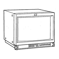
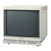
Overview of the monitor's key features and capabilities.

Location and Function of Parts and Controls

Front

Identification and function of controls and indicators on the front panel.

Rear Pane

Identification and function of connectors and ports on the rear panel.

SECTION 3 SET-UP ADJUSTMENTS

3-1. PREPARATIONS (1)

Initial steps and preparations for making set-up adjustments.

3-2. Preparation (2). Initialization

Second part of preparation and initialization for adjustments.

3-3. Writing model data

Procedure for writing model-specific data into the service mode.

3-6. Convergence adjustment (1)

First part of the procedure for adjusting convergence.

3-7. Deflection yoke neck rotation adjustment

Procedure for rotating the deflection yoke to correct misconvergence.

3-8. Convergence adjustment (2)

Second part of the procedure for adjusting convergence.

3-10. White balance adjustment

Steps for calibrating the monitor's white balance.

3-13. Focus adjustment

Procedure for adjusting the monitor's focus.

SECTION 4 SAFETY RELATED ADJUSTMENT

4-1. CONFIRAMATION OF +B MAXIMUM

Checking the maximum +B voltage level for safety.

4-2. CONFIRAMATION OF HOLD-DOWN CIRCUIT

Verifying the hold-down circuit operation for safety.

SECTION 5 CIRCUIT ADJUSTMENTS

5-1. A BOARD ADJUSTMENT

Adjustments performed on the A circuit board.

ADJUSTMENT OF DEFLECTION SYSTEM

Procedures for adjusting the deflection system for optimal image geometry.

SECTION 6 DIAGRAMS

6-1. BLOCK DIAGRAMS (1)

First part of block diagrams illustrating system architecture.

BLOCK DIAGRAMS (2)

Second part of block diagrams illustrating system architecture.

6-3. CIRCUIT BOARDS LOCATION

Diagram showing the physical location of circuit boards within the unit.

6-4. PRINTED WIRING BOARDS AND SCHEMATIC DIAGRAMS

Detailed layout of printed wiring boards and schematic diagrams.

SECTION 8 ELECTRICAL PARTS LIST

Related product manuals