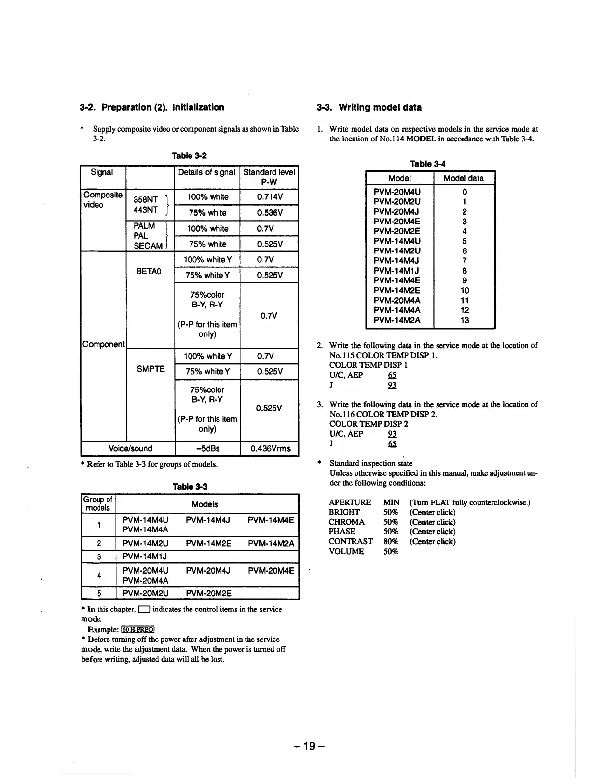
3-2. Preparation (2). Initialization
* Supply composite video or component signals as shown in Table
3-2.
Table3-2
Signal Details of signal Standard level
P-W
Composite
358NT }
100% white 0.714V
video
443NT
75%white 0.536V
PALM }
100% white 0.7V
PAL
SECAM
75%white 0.525V
100% whiteY 0.7V
BETA0
75%whiteY 0.525V
75%color
B-Y, R-Y
0.7V
(P-P for this item
only)
Component
100%whiteY 0.7V
SMPTE
75%whiteY 0.525V
75%color
B-Y, R-Y
0.525V
(P-P for this item
only)
Voice/sound -5dBs 0.436Vrms
* Refer to Table 3-3 for groups of models.
Table 3-3
Group of
Models
models
1
PVM-14M4U PVM-14M4J PVM-14M4E
PVM-14M4A
2 PVM-14M2U PVM-14M2E
PVM-14M2A
3
PVM-14M1J
4
PVM-20M4U PVM-20M4J PVM-20M4E
PVM-20M4A
5
PVM-20M2U PVM-20M2E
* In this chapter, D indicates the control items in the service
mode.
Example: !60 H-FREO!
* Before turning off the power after adjustment in the service
mode, write the adjustment data. When the power is turned off
before writing, adjusted data will all be lost.
3-3. Writing model data
l. Write model data on respective models in the service mode at
the location ofNo.114 MODEL in accordance with Table 3-4.
Table 3-4
Model Model data
PVM-20M4U
0
PVM-20M2U 1
PVM-20M4J 2
PVM-20M4E
3
PVM-20M2E 4
PVM-14M4U 5
PVM-14M2U
6
PVM-14M4J 7
PVM-14M1J
8
PVM-14M4E
9
PVM-14M2E 10
PVM-20M4A 11
PVM-14M4A 12
PVM-14M2A 13
2. Write the following data in the service mode at the location of
No.115 COLOR TEMP DISP 1.
COLOR TEMP DISP 1
U/C,AEP
~
J 2l
3. Write the following data in the service mode at the location of
No.116 COLOR TEMP DISP 2.
COLOR TEMP DISP 2
U/C,AEP 2l
J
~
* Standard inspection state
Unless otherwise specified in this manual, make adjustment un-
der the following conditions:
APERTURE
BRIGHT
CHROMA
PHASE
CONTRAST
VOLUME
MIN (Tum FLAT fully counterclockwise.)
50% (Center click)
50% (Center click)
50% (Center click)
80% (Center click)
50%
-19-