SECTION 4
SAFETY RELATED ADJUSTMENT
When the parts (with aB ,Ci mark on the circuit diagram) shown
below are replaced, confirm the matters described in items 4-1 and
4-2 shown below.
BR1536
Ci R551, R506, R519, R518, R516, R515, R508, R517, R1560,
Rl537, C549, C512, C513, C523, C592, D501, D533, QSOO,
Q511, IC500, and IC507
When the following parts are replaced, check the +B voltage:
IC600, IC602, D610, C615, C631, C621, C632, and T603
Confirmation procedure
I. Input 120 VAC.
2. Input a monoscope signal, and minimize CONTRAST and
BRIGHT.
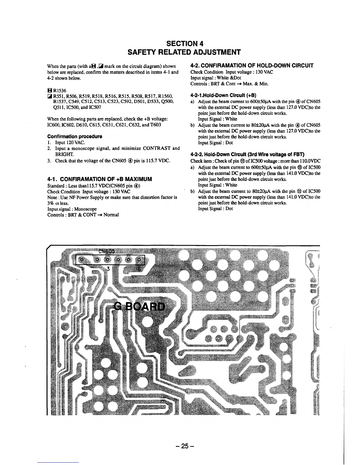
3. Check that the voltage of the CN605 © pin is 115.7 VDC.
4-1. CONFIRAMATION OF +B MAXIMUM
Standard : Less than115.7 VDC(CN605 pin ©)
Check Condition Input voltage: 130 VAC
Note: Use NF Power Supply or make sure that distortion factor is
3% or less.
Input signal : Monoscope
Controls : BRT & CONT
➔
Normal
4-2. CONFIRAMATION OF HOLD-DOWN CIRCUIT
Check Condition Input voltage : 130 VAC
Input signal : White &Dot
Controls : BRT & Cont
➔
Max. & Min.
4-2-1.Hold-Down Circuit (+B)
a) Adjust the beam current to 600±50µA with the pin © of CN605
with the external DC power supply (less than 127 .0 VDC)to the
point just before the hold-down circuit works.
Input Signal : White
b) Adjust the beam current to 80±20µA with the pin © of CN605
with the external DC power supply (less than 127 .0 VDC)to the
point just before the hold-down circuit works.
Input Signal : Dot
4-2-2. Hold-Down Circuit (3rd Wire voltage of FBT)
Check item : Check of pin ® ofIC500 voltage : more than 110.0VDC
a) Adjust the beam current to 600±50µA with the pin ® of IC500
with the external DC power supply (less than 141.0 VDC)to the
point just before the hold-down circuit works.
Input Signal : White
- b) Adjust the beam current to 80±20µA with the pin ® of IC500
with the external DC power supply (less than 141.0 VDC)to the
point just before the hold-down circuit works.
Input Signal : Dot
-25-