·-·· ................... ---. ······· .................................................. .
-51-
SONV-SP00401 /DRUCK 9
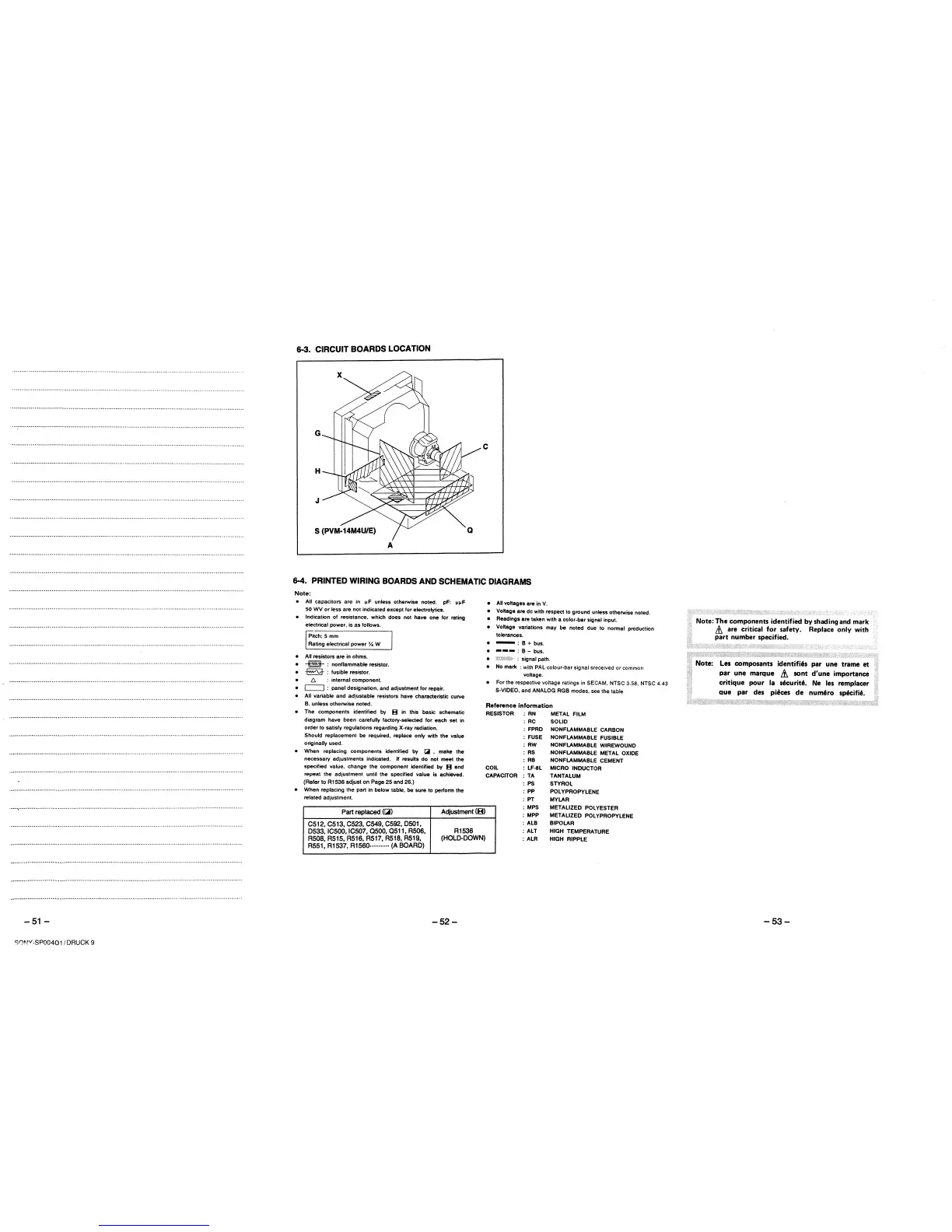
6-3. CIRCUIT BOARDS LOCATION
C
A
6-4. PRINTED WIRING BOARDS AND SCHEMATIC DIAGRAMS
Note:
• All capacitors are in l'F unless otherwise noted. pF: l'l'F
50 WV or less are not indicated except for electrolytics.
• Indication of resistance, which does not have one for rating
electrical power, is as follows.
Pitch: 5 mm
Rating electrical power ¼ W
• All resistors are in ohms.
• --m-: nonflammable resistor.
•
~
: fusible resistor.
• t:,. : internal component.
• c==J : panel designation, and adjustment for repair.
• All variable and adjustable resistors have characteristic curve
B. unless otherwise noted.
• The components identified by B in this basic schematic
diagram have been carefully factory-selected for each set in
order to satisfy regulations regarding X-ray radiation.
Should replacement be required, replace only with the value
originally used.
• When replacing components identified by [;iii , make the
necessary adjustments indicated. If results do not meet the
specified value. change the component identified by B and
repeat the adjustment until the specified value is achieved.
(Refer to R1536 adjust on Page 25 and 26.)
• When replacing the part in below table, be sure to perfonn the
related adjustment.
Part replaced (~)
Adjustment (B)
C512, C513, C523, C549, C592, 0501,
0533, ICS00, IC507, asoo, Q511, R506,
R1536
R508,R515,R516,R517,R518,R51~,
(HOLD-DOWN)
R551, R1537, R1560·······"·· (A BOARD)
-52-
• All voltages are in V.
• Voltage are de with respect to ground unless otherwise noted.
• Readings are taken with a color-bar signal input.
• Voltage variations may be noted due to nonnal production
tolerances.
• -= B+bus.
• --- : B - bus.
• ............ ,-.,.::.,. • signal path.
• No mark : with PAL colour-bar signal sreceived or common
voltage.
• For the respective voltage ratings in SECAM, NTSC 3.58, NTSC 4.43
$-VIDEO, and ANALOG RGB modes, see the table
Reference information
RESISTOR : RN METAL FILM
COIL
CAPACITOR
: RC
: FPRD
: FUSE
: AW
: RS
: RB
: LF-8L
: TA
: PS
: pp
: PT
: MPS
: MPP
: ALB
: ALT
: ALR
SOLID
NONFLAMMABLE CARBON
NONFLAMMABLE FUSIBLE
NONFLAMMABLE WIREWOUND
NONFLAMMABLE METAL OXIDE
NONFLAMMABLE CEMENT
MICRO INDUCTOR
TANTALUM
STYROL
POLYPROPYLENE
MYLAR
METALIZED POL VESTER
METALIZED POLYPROPYLENE
BIPOLAR
HIGH TEMPERATURE
HIGH RIPPLE
Note: Les composants identifi6s par une trame et •
par une marque &. sont d'une importance
critique pour la s6curit6. Ne les remplacer
aue par des piices de num6ro sp6cifi6.
-53-