* The above adjustment may affect the landing, so after adjust•
ment, check the landing again.
7. Paint-lock the knobs after adjustment.
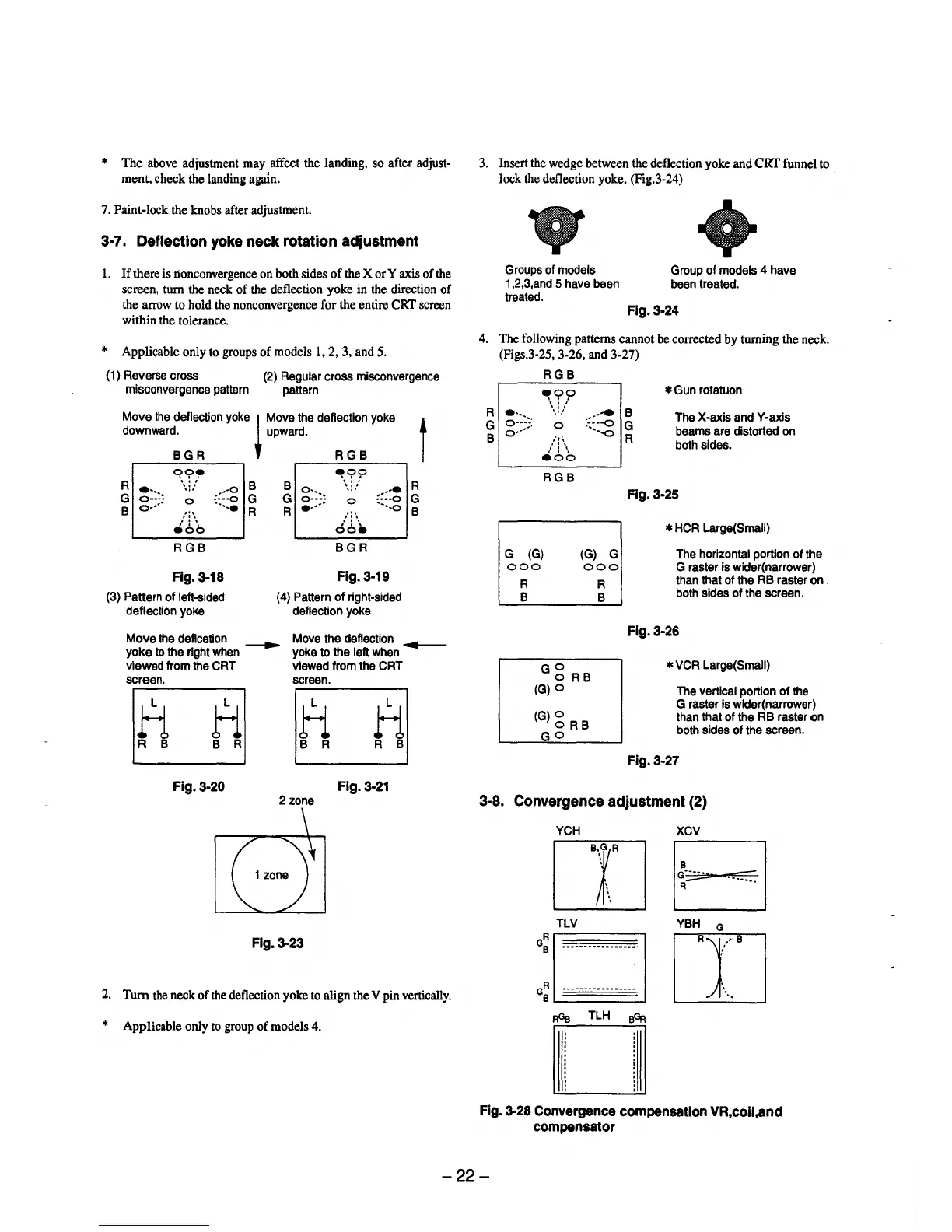
3-7. Deflection yoke neck rotation adjustment
1. If there is lionconvergence on both sides of the X or Y axis of the
screen, turn the neck of the deflection yoke in the direction of
the arrow to hold the nonconvergence for the entire CRT screen
within the tolerance.
* Applicable only to groups of models 1, 2, 3, and 5.
(1) Reverse cross
misconvergence pattern
(2) Regular cross misconvergence
pattern
Move the deflection yoke
~
Move the deflection yoke t
downward. upward.
BGR RGB
R
~?,.
B B
9!,??
R
~:::~
...
:::::; :;:::~
., .
::::~
...
., .
G
0
G
G
0
G
B
o•···
...
·-..•
R R
•····
'"
···-o
B
,': \ ,': \
e6b
oo•
RGB BGR
Fig. 3-18
Fig.3-19
(3) Pattern of left•sided (4) Pattern of right•sided
deflection yoke deflection yoke
Move the deflcetion
~
Move the deflection
~
yoke to the right when yoke to the left when
viewed from the CRT viewed from the CRT
screen.
screen.
H
ti
ti
H
R B B R
B R
R B
Fig. 3-20 Fig. 3-21
2 zone
Fig. 3-23
2. Tum the neck of the deflection yoke to align the V pin vertically.
* Applicable only to group of models 4.
3. Insert the wedge between the deflection yoke and CRT funnel to
lock the deflection yoke. (Fig.3-24)
Groups of models Group of models 4 have
1,2,3,and 5 have been been treated.
treated.
Flg.3-24
4. The following patterns cannot be corrected by turning the neck.
(Figs.3-25, 3·26, and 3-27)
RGB
~??
. ''
'·'-'
0
;,·,
,' : \
eoo
RGB
.•···• B
··•·o G
····-o
R
* Gun rotatuon
The X-axis and Y•axis
beams are distorted on
both sides.
Fig. 3-25
* HCA Large(Small)
G (G)
(G) G The horizontal portion of the
G raster is wider(narrower)
than that of the RB raster on .
both sides of the screen.
000
000
R
B
G g RB
(G)O
(G)g RB
GO
R
B
Fig. 3-26
* VCR Large(Small)
The vertical portion of the
G raster is wider(narrower)
than that of the RB raster on
both sides of the screen.
Fig.3-27
3-8. Convergence adjustment (2)
YCH XCV
rn EJ
a:
□
T·L~·-··········
ITJYBH
0
+
GR •••••••••••••••••. J._
B
~
~
TLH
~
Fig. 3-28 Convergence compensation VR,coil,and
compensator
-22-