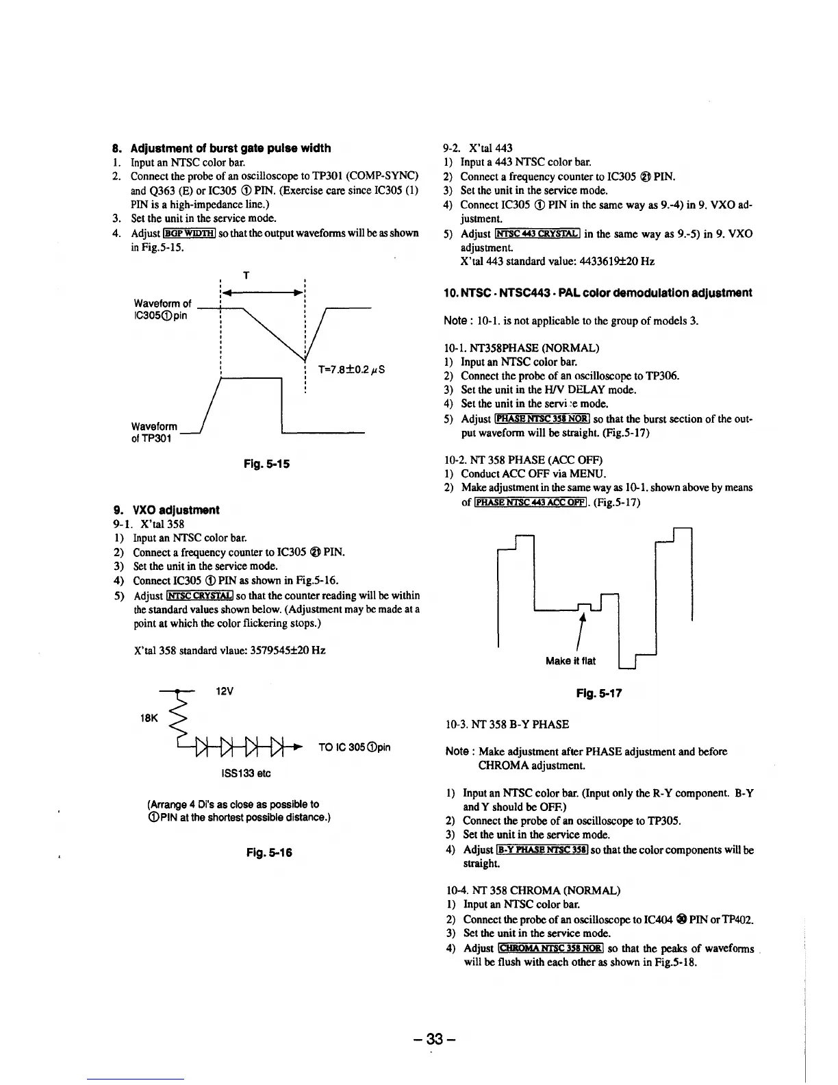
8. Adjustment of burst gate pulse width
I. Input an NTSC color bar.
2. Connect the probe of an oscilloscope to TP301 (COMP-SYNC)
and Q363 (E) or IC305 (i) PIN. (Exercise care since IC305 (1)
PIN is a high-impedance line.)
3. Set the unit in the service mode.
4. Adjust !BOP WIDTH I so that the output waveforms will be as shown
in Fig.5-15.
T
'
'
◄
..
1-----~IJJ
►:
Waveform of --+--, '
IC305(Dpin
Wa,efo,mj
ofTP301
9. VXO adjustment
9-1. X'tal 358
Fig. 5-15
1) Input an NTSC color bar.
T=7.8±0.2µS
2) Connect a frequency counter to IC305 Ii) PIN.
3) Set the unit in the service mode.
4) Connect IC305 (i) PIN as shown in Fig.5-16.
5) Adjust !NTSC CRYSTAL! so that the counter reading will be within
the standard values shown below. (Adjustment may be made at a
point at which the color flickering stops.)
X'tal 358 standard vlaue: 3579545±20 Hz
18K
TO IC 305 (i)pin
l8S133 etc
(Arrange 4 Di's as close as possible to
(i)PIN at the shortest possible distance.)
Flg.5-16
9-2. X'tal 443
I) Input a 443 NTSC color bar.
2) Connect a frequency counter to IC305 Ii) PIN.
3) Set the unit in the service mode.
4) Connect IC305 (D PIN in the same way as 9.-4) in 9. VXO ad-
justment.
5) Adjust ..,.iNTS=c=-44-:-=3-=ca:=y""s==TAL=-il in the same way as 9.-5) in 9. VXO
adjustment.
X'tal 443 standard value: 4433619±20 Hz
1 o. NTSC . NTSC443 . PAL color demodulation adjustment
Note : 10-1. is not applicable to the group of models 3.
10-1. NT358PHASE (NORMAL)
I) Input an NTSC color bar.
2) Connect the probe of an oscilloscope to TP306.
3) Set the unit in the HIV DELAY mode.
4) Set the unit in the servi :e mode.
5) Adjust iPHASB NTSC 358 NOR! so that the burst section of the out-
put waveform will be straight. (Fig.5-17)
10-2. NT 358 PHASE (ACC OFF)
1) ConductACC OFF via MENU.
2) Make adjustment in the same way as 10-1. shown above by means
of !PHASE NTSC 443 ACC OFP i. (Fig.5-17)
Make it flat
Fig. 5-17
10-3. NT 358 B-Y PHASE
Note : Make adjustment after PHASE adjustment and before
CHROMA adjustment.
1) Input an NTSC color bar. (Input only the R-Y component. 8-Y
and Y should be OFF.)
2) Connect the probe of an oscilloscope to TP305.
3) Set the unit in the service mode.
4) Adjust IB-Y PHASB NTSC 358 i so that the color components will be
straight.
10-4. NT 358 CHROMA (NORMAL)
1) Input an NTSC color bar.
2) Connect the probe of an oscilloscope to IC404 ® PIN or TP402.
3) Set the unit in the service mode.
4) Adjust !CHROMA NTSC 358 NORI so that the peaks of waveforms
will be flush with each other as shown in Fig.5-18.
-33-