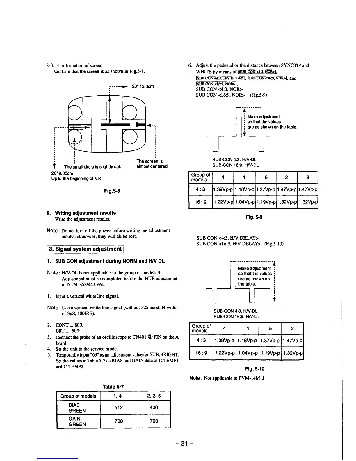
8-3. Confirmation of screen
Confirm that the screen is as shown in Fig.5-8.
,------ 20" 12.3cm
'
l The small circle is slightly cut.
20"9.00cm
Up to the beginning of silk
Flg.5-8
9. Writing adjustment results
Write the adjustment results.
◄--
'
The screen is
almost centered.
Note : Do not turn off the power before writing the adjustment
results; otherwise, they will all be lost.
I 3. Signal system adjustment I
1. SUB CON adjustment during NORM and HIV DL
Note : H/V-DL is not applicable to the group of models 3.
Adjustment must be completed before the HUE adjustment
of NTSC358/443.PAL.
1. Input a vertical white line signal.
Note : Use a vertical white line signal (without 525 burst; H width
of 3µS; lOOIRE).
2. CONT ... 80%
BRT .... 50%
3. Connect the probe of an oscilloscope to CN401 @PIN on the A
board.
4. Set the unit in the service mode.
5. Temporarily input "69" as an adjustment value for SUB.BRIGHT.
Set the values in Table 5-7 as BIAS and GAIN data ofC.TEMPl
and C.TEMP2.
Table 5-7
Group of models
1, 4 2,3,5
BIAS
512
400
GREEN
GAIN
700
700
GREEN
6. Adjust the pedestal or the distance between SYNCTIP and
WHITE by means of !SUB CON <4:3, NOR>L
!SUB CON <4:3, HIV DELAY!, !SUB CON <16:9, NOR>!, and
!SUB CON <16:9. NOR>I.
SUB CON <4:3. NOR>
SUB CON <16:9. NOR> (Fig.5-9)
.l -------
: Make adjustment
: so that the values
i are as shown on the table.
Group of
models
4:3
16:9
'
'f
SUB-CON 4:3. HN-DL
SUB-CON 16:9. HN-DL
4 1
5
1.39Vp-p 1.16Vp-p 1.37Vp-p
1.22Vp-p
1.04Vp-p
1.19Vp-p
Flg.5-9
SUB CON <4:3. HIV DELAY>
2
1.47Vp-p
1.32Vp-p
SUB CON <16:9. HIV DELAY> (Fig.5-10)
Group of
models
---------------- .l
Make adjustment :
so that the values i
are as shown on :
the table. :
'
'
'
'
•
SUB-CON 4:3. HN-DL
SUB-CON 16:9. HN-DL
4 1
5 2
3
1.47Vp-p
1.32Vp-~
4:3
1.39Vp-p 1.16Vp-p
1.37Vp-p 1.47Vp-p
16:9
1.22Vp-p
1.04Vp-p 1.19Vp-p
Flg.5-10
Note : Not applicable to PVM-14MlJ
1.32Vp-p
-31-