L IIP
>-
<
...J"'
i¼l.;; *
>-
i
:n
~
=
1P
-ONLY ---7
--7 !
s
T!ON
I
I
I
I
I
I
I
I
I
I
I
I
I
_____ __J
CN303
-5 MICRO WHT 12P
' -
' -'
u ,w
0
J IJJ
>-
"'
z
Q
u >- "'
>-;:;
JO
z J::
~
I
iii
:::,
a,
I
I <0
<
>
I:::,
:<
u
z
>-
"' I
:i:
I _, -,.
"'
.. ...
.,
en
~:
~
fl!GITAL OPTION
lEMOTE OPT I ON
CN30B
J WHT-L 4P
l
//'
___ __,
V901
PICTURE
TUBE
SP
....
a u CjJ
w
z 15
..
CN201
5-M!C REtl
3P
CN401
5-MICRO WHT BP
CN502
M f Nf 6P
WHT
CNSOS
3P 5-MICRO WHY
Ht
H+
H-
3
H-
v-
V+
CN501
ElY 6P
WHT
I
V.P
I
R OUT
2
GOUT 3
BOUT
4
12V 5
GN!)
6
IK
7
GNIJ
8
62
I
IBOV 2
GNIJ 3
NC
4
HI 5
H2
6
H.FREQ I
12V
2
GN!)
3
I
2
3
4
5
6
7
8
I
2
3
4
5
6
-
FOR
CHECK
V.P
R OUT
GOUT
B OUT
12V
GN!)
IK
GN!)
G2
IBOV
GN!l
NC
HI
-
CN70 I
CN703
FASTEN
S-M I CRO WHT BP
C
CN702
WHT MIN! 6P
'i :;;;---,~,-_-_iJ
H2
r-J,o
I IG41
11 I
I
I
I
I I l
r----::7 r I I I
CN50B I I HVb--- PICTURE TUBE I I I
-- _____ ..J
I
I
I
I
WHT 2P );l
~
I I Fv'----------<i I I I
M1N1
~ ~
1
1
rso, PVM-14M2U/M2E/M2A I I
i:. > (FBTI ONLY I
IL-------- --- JI
----1--1----1--,_-_-___________ _J 7 !
Focus:
VR I:
I PVM---14M4U/M4E/M4A ONLY -;J J
L----------------------
-50-
SONY-SP00401 / DRUCK 8
MEMO
-51-
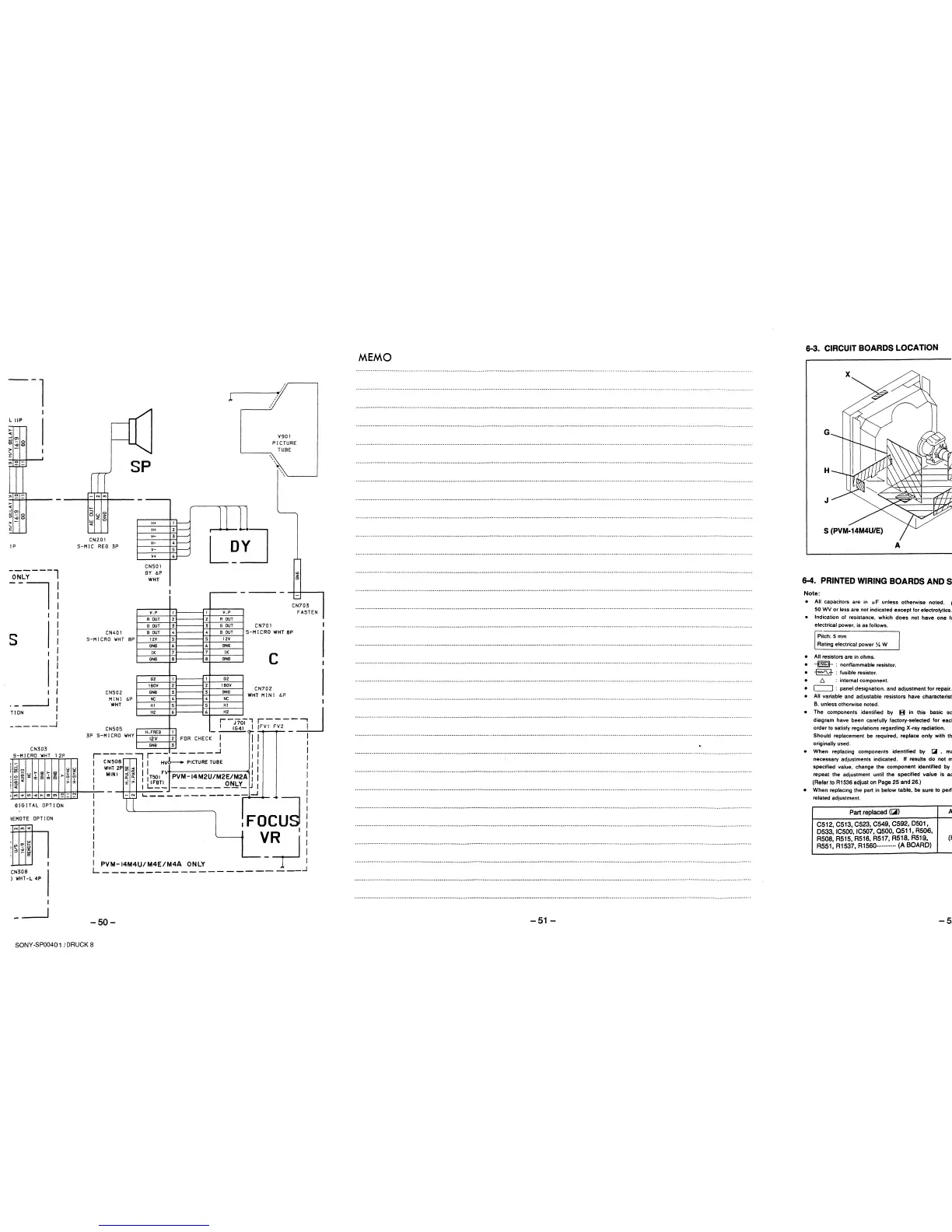
6-3. CIRCUIT BOARDS LOCATION
A
6-4. PRINTED WIRING BOARDS ANDS
Note:
• All capacitors are in µF unless otherwise noted. 1
50 WV or less are not indicated except for electrolytics.
• Indication of resistance. which does not have one le
electrical power, is as follows.
Pitch: 5 mm
Rating electrical power ¼ W
• All resistors are in ohms.
•
~
: nonflammable resistor.
• -§a- : fusible resistor.
• 6. : internal component.
• [===::J : panel designation. and adjustment for repair.
• All variable and adjustable resistors have characteristi
B. unless otherwise noted.
• The components identified by B in this basic sc
diagram have been carefully factory-selected for eact
order to satisfy regulations regarding X-ray radiation.
Should replacement be required, replace only with th,
originally used.
• When replacing components identified by IA , ma
necessary adjustments indicated. II results do not m
specified value, change the component identified by
repeat the adjustment until the specified value is ac
(Refer to R1536 adjust on Page 25 and 26.)
• When replacing the part in below table, be sure to perfc
related adjustment.
Part replaced ((;iii)
C512, C513, C523, C549, C592, D501,
D533, IC500, IC507, 0500, 0511, R506,
R508,R515,R516,R517,R518,R51~,
R551, R1537, R1560·······"·· (A BOARD)
A
(I-
-5: