10-13. PAL PHASE (ACC OFF)
Note : 10-13. is not applicable to the group of models 3.
1) Conduct ACC OFF via MENU.
2) Adjust IPHASBPALACCOPFI in the same way as 10-12-4).
10-14. PALB-YPHASE
Note : Be sure to set ACC in the ON position before this adjust-
ment.
1) Input a PAL SP color bar.
2) Connect the probe of an oscilloscope to TP305.
3) Set the unit in the service mode.
4) Adjust IB-YPHASBPAL! so that the waveform of the R-Y anti-
PAL signal will be "O." (Fig.5-26)
Anti-PAL signal
8-Y (90. /90. )
•
•
-0-
*The signal waveform differs slightly every hour.
Adjust it to "0."
Fig. 5-26 B-Y OUT
10-15. PAL CHROMA (NORMAL)
l) Input a PAL color bar.
2) Connect the probe of an oscilloscope to IC404 ® PIN or TP402.
3) Set the unit in the service mode.
4) AdjustlCHROMA PAL NORI so that the peaks of waveforms will he
flush with each other. (Fig.5-27)
10-16. PAL CHROMA (ACC OFF)
Note : 10-16. is not applicable to the group of model 3.
l) Conduct ACC OFF via MENU.
2) Adjust I CHROMA PAL ACC OPFI in the same way as 10-15-4 ).(Fig.5-
27)
Make Band D flush with each other.
A
__ D __ -----------·
B
C
t
40mVmax.
Fig. 5-27
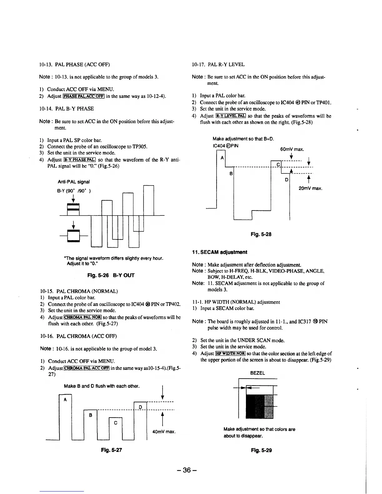
10-17. PAL R-Y LEVEL
Note : Be sure to set ACC in the ON position before this adjust-
ment.
l) Input a PAL color bar.
2) Connect the probe of an oscilloscope to IC404 ® PIN or TP40l.
3) Set the unit in the service mode.
4) Adjust IR-YLEVBLPAL! so that the peaks of waveforms will be
flush with each other as shown on the right. (Fig.5-28)
Make adjustment so that B=D.
IC404@PIN
60mV max.
A
+
B
D
20mVmax.
Fig. 5-28
11. SECAM adjustment
Note : Make adjustment after deflection adjustment.
Note : Subject to H-FREQ, H-BLK, VIDEO-PHASE, ANGLE,
BOW, H-DELAY, etc.
Note: 11. SECAM adjustment is not applicable to the group of
models 3.
11-1. HP WIDTH (NORMAL) adjustment
1) Input a SECAM color bar.
Note : The board is roughly adjusted in 11-1., and IC317 ® PIN
pulse width may be used for control.
2) Set the unit in the UNDER SCAN mode.
3) Set the unit in the service mode.
4) Adjust IHP WIDTH NORI so that the color section at the left edge of
the upper portion of the screen is about to disappear. (Fig.5-29)
BEZEL
Make adjustment so that colors are
about to disappear.
Fig. 5-29
-36-