11-2. Writing HP.WIDTH (NORMAL) data
Note : Not applicable to groups of models 1, 2, 4, and 5.
1) Set the unit in the service mode.
2) Input 102 to HP.WIDTH (NOR).
11-3. HP POSITION adjustment
Note : 11-3. is not applicable to the group of models 3.
1) Input a SECAM color bar.
2) Set the HV-DL mode.
3) Set the unit in the service mode.
4) Adjust !HP POSmONI as shown in Fig.5-30.
Note: The same as 11-3. The phase relationship between the
beginning of IC317 @) PIN pulse and the input VIDEO
signal may be used for control.
/ H-SYNC
L
·····················••.•.••.•C• .. w.•.,.,.,.,.,.,.•.,.,. ,.__ V•SYNC
.... of plciun, -I
t
Bring the BLK edge to this
position by HP POSITION.
I-Beglaal"I) of plctu,e
I
Bring the BLK edge to this
position by HP WIDTH HN.
Fig. 5-30
11-4. HP WIDTH (H/V-DL) adjustment
Note : 11-4. is not applicable to the group of models 3.
1) Input a SECAM color bar.
2) Set the unit in the HV-DELAY mode.
3) Set the unit in the service mode.
4) Adjust !HPWID11i H/V-DELAYI as shown in Fig.5-30. (Note: Check
HP POSITION. If it is not in position, repeat 2) and 3).)
11-5. SECAM COL BALANCE
Note : 11-5. is not applicable to the group of models 3.
1) Input a SECAM color bar.
2) Connect the probe of an oscilloscope to TP306.
3) Set the unit in the service mode.
4) Adjust !SE.CAM COLOR BALANCER-YI so that the level in the ach-
romatic color will be straight.
5) Connect the probe of an oscilloscope to TP305.
6) Adjust !SECAMCOLORBALANCEB-YI so that the level in the ach-
romatic color will be straight.
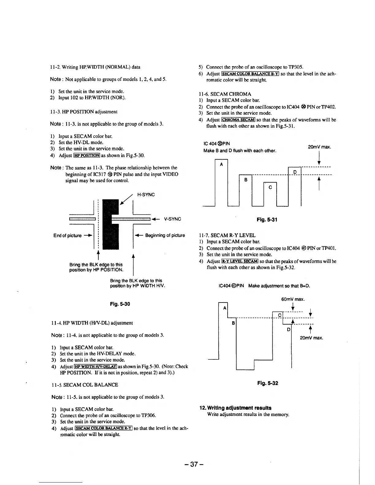
11-6. SECAM CHROMA
1) Input a SECAM color bar.
2) Connect the probe of an oscilloscope to IC404 ® PIN orTP402.
3) Set the unit in the service mode.
4) Adjust !CHROMA SECAM! so that the peaks of waveforms will be
flush with each other as shown in Fig.5-31.
IC 404®PIN
Make Band D flush with each other.
A
D
--------------------
B
C
Fig. 5-31
11-7. SECAM R-Y LEVEL
l) Input a SECAM color bar.
20mVmax.
~
t
2) Connect the probe of an oscilloscope to IC404 @PIN orTP401.
3) Set the unit in the service mode.
4) Adjust IR-YLEVBL SECAMI so that the peaks of waveforms will be
flush with each other as shown in Fig.5-32.
IC404@PIN Make adjustment so that B=D.
60mVmax.
t
t
----------·-·
B
... --------
D
t
20mVmax.
Fig. 5-32
12. Writing adjustment results
Write adjustment results in the memory.
-37-