SECTION 5
CIRCUIT ADJUSTMENTS
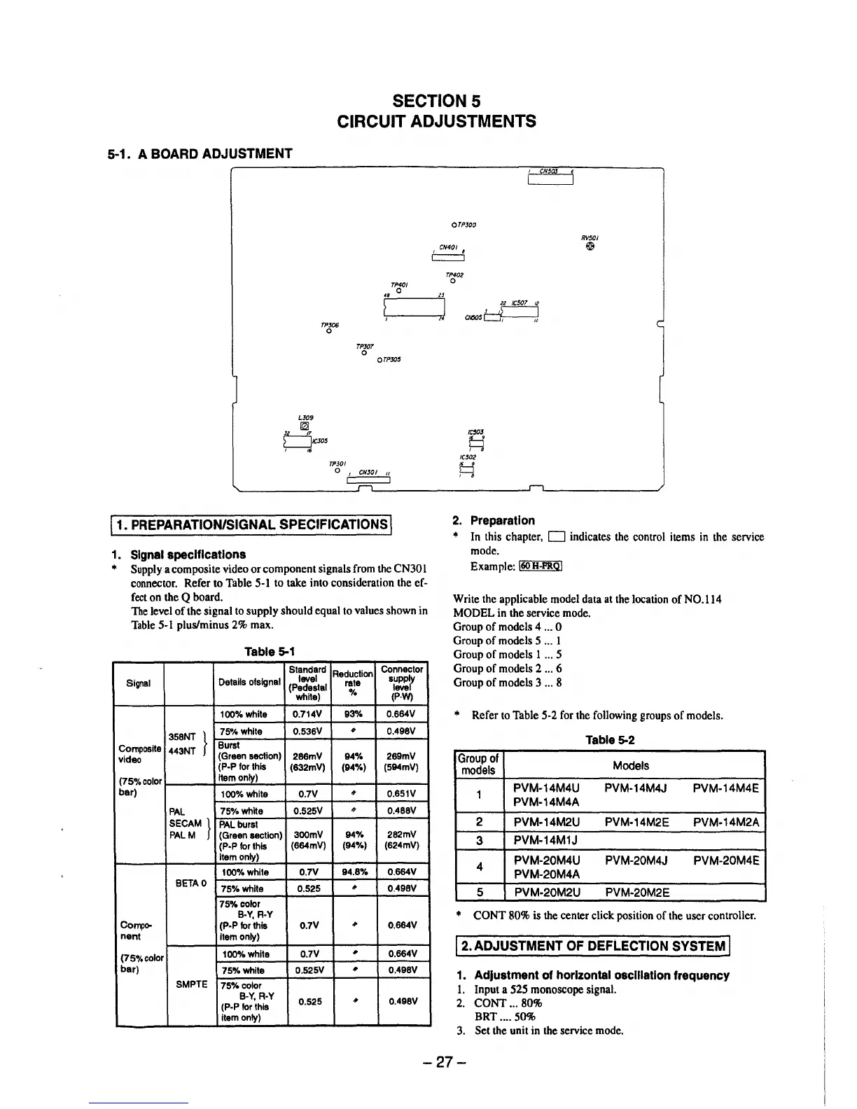
5-1. A BOARD ADJUSTMENT
TPJ06
0
LJ09
~
µ_.J!,
L__JICJ05
, ,.
TPJ0I
TPXJT
0
TP4C/
0
OTPXJ5
0
1
CNJOI 11
11. PREPARATION/SIGNAL SPECIFICATIONS I
1. Signal specifications
• Supply a composite video or component signals from the CN30 I
connector. Refer to Table 5-1 to take into consideration the ef-
fect on the Q board.
The level of the signal to supply should equal to values shown in
Table 5-1 plus/minus 2% max.
Table 5-1
Standard
Reduction
Connector
Signal
Details ofsignal
level
rate
supply
(Pedestal
level
white)
%
(P.W)
100%white
0.714V 93% 0.664V
}
7S°/4 white
0.536V
#
0.498V
358NT
Composite
443NT
Burst
video
(Green section)
286mV
94% 289mV
(P-P for this
(632mV) (94%) (594mV)
(75o/ocolor
item only)
bar)
100%white 0.7V
#
0.651V
PAL
75%white
0.525V
#
0.488V
SECAM}
PAL burst
PALM (Green section)
300mV
94% 282mV
(P•P for this
(664mV)
(94%) (624mV)
item only)
100%white 0.7V
94.8%
0.664V
BETA0
75%whlte 0.525
•
0.498V
75%color
B•Y, R•Y
Compo-
(P-P for this
0.7V
•
0.664V
nent
Item only)
(75%color
100%white
0.7V
•
0.664V
bar)
75%white
0.525V
,,
0.498V
SMPTE
75%color
B-Y, R-Y
0.525
•
0.498V
(P-P for this
item only)
,.
OTPJ00
TP402
0
22 IC507 12
,,~
CN505~
IC50J
□
, 8
IC502
,. 9
CJ
, 8
2. Preparation
CN50J
RV501
@&
• In this chapter, D indicates the control items in the service
mode.
Example: l60H-PRQ!
Write the applicable model data at the location of NO.114
MODEL in the service mode.
Group of models 4 ... 0
Group of models 5 ... 1
Group of models 1 ... 5
Group of models 2 ... 6
Group of models 3 ... 8
• Refer to Table 5-2 for the following groups of models.
Table 5-2
Group of
Models
models
1
PVM-14M4U PVM-14M4J
PVM-14M4E
PVM-14M4A
2
PVM-14M2U PVM-14M2E PVM-14M2A
3
PVM-14M1J
4
PVM-20M4U PVM-20M4J PVM-20M4E
PVM-20M4A
5 PVM-20M2U PVM-20M2E
• CONT 80% is the center click position of the user controller.
12. ADJUSTMENT OF DEFLECTION SYSTEM I
1. Adjustment of horizontal osclllatlon frequency
1. Input a 525 monoscope signal.
2. CONT ... 80%
BRT .... 50%
3. Set the unit in the service mode.
-27-