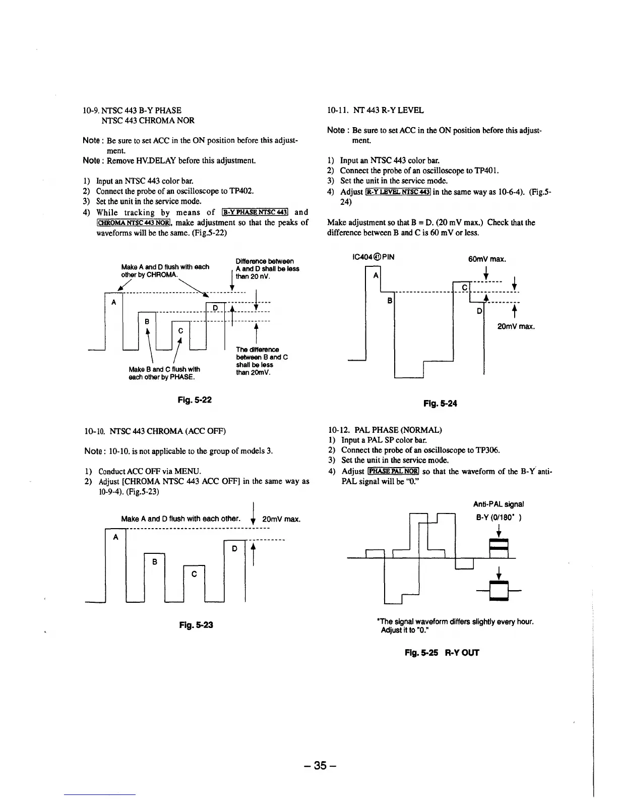
10-9. NTSC 443 B-Y PHASE
NTSC 443 CHROMA NOR
Note : Be sure to set ACC in the ON position before this adjust-
ment.
Note : Remove HY.DELAY before this adjustment.
1) Input an NTSC 443 color bar.
2) Connect the probe of an oscilloscope to TP402.
3) Set the unit in the service mode.
4) While tracking by means of IB-YPHASBNTSC443! and
!CHROMANTSC443NOR!. make adjustment so that the peaks of
waveforms will be the same. (Fig.5-22)
Difference between
Make A and D flush with each A and D shall be less
other by CHROMA. i than 20 nV.
✓-----------
~
--------i
A B ····-····· .•••. --~--
l~~~~~-~~~~
\ IC The jerence
\ between B and C
shall be less
than2omv.
Make B and C flush with
each other by PHASE.
Fig. 5-22
10- JO. NTSC 443 CHROMA (ACC OFF)
Note : 10-10. is not applicable to the group of models 3.
1) ConductACC OFF via MENU.
2) Adjust [CHROMA NTSC 443 ACC OFF] in the same way as
10-9-4). (Fig.5-23)
Make A and D flush with each other.
~
20mVmax.
A
B
D
t
C
Fig.5-23
10-11. NT 443 R-Y LEVEL
Note : Be sure to set ACC in the ON position before this adjust-
ment.
1) Input an NTSC 443 color bar.
2) Connect the probe of an oscilloscope to TP401.
3) Set the unit in the service mode.
4) Adjust !R-YLBVBLNTSC443! in the same way as 10-6-4). (Fig.5-
24)
Make adjustment so that B = D. (20 mV max.) Check that the
difference between B and C is 60 m V or less.
IC404@PIN
60mVmax.
20mVmax.
Flg.5-24
10-12. PAL PHASE (NORMAL)
1) Input a PAL SP color bar.
2) Connect the probe of an oscilloscope to TP306.
3) Set the unit in the service mode.
4) Adjust !PHASE PAL NOR! so that the waveform of the B-Y anti-
PAL signal will be "O."
Anti-PAL signal
B-Y (0/180" )
+
+
-0-
*The signal waveform differs slightly every hour.
Adjust it to "0."
Fig. 5-25 R-Y OUT
-35-