EasyManuals Logo

Sony Trinitron PVM-14L4 Service Manual

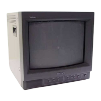
Sony Trinitron PVM-14L4
193 pages
To Next Page IconTo Next Page
To Previous Page IconTo Previous Page
Page #38 background imageLoading...
Page #38 background image
2-4.
Writing
Model
Data
1.
Write
model
data
on
respective
models
in
the
service
mode
at
the
location
of
No.114
MODEL
in
accordance
with
Table
2-4,
PVM-20L4
ost
PYM-14L3/44L4
PVM-20L5
0
1
2
PVM-14L5
3
4
5
2.
Write
the
following
data
in
the
service
mode
at
the
location
of
No.115
COLOR
TEMP
DISP
1.
COLOR
TEMP
DISP
t
U/C,
AEP
65
J
23
3.
Write
the
following
data
in
the
service
mode
at
the
location
of
No.116
COLOR
TEMP
DISP
2.
COLOR
TEMP
DISP
2
UIC,
AEP
ky
J
5
x
Standard
inspection
state
Unless
otherwise
specified
in
this
manual,
make
adjust-
ment
under
the
following
conditions:
APERTURE
MIN
(Turn
FLAT
fully
counterclockwise.)
BRIGHT
50%
(Center
click)
CHROMA
50%
(Center
click)
PHASE
50%
(Center
click)
CONTRAST
80%
(Center
click)
VOLUME
50%
(Center
click)
2-16
PVM-D20L.5J
PVM-Dt4L5J
2-5.
Picture
Output
1.
AC
input
voltage
setting
1.
Input
VIDEO
signals
and
AUDIO
signals
to
respective
terminals
on
the
connector
panel.
2.
Set
the
sliduck
AC
voltage
as
shown
in
Table
2-5.
PYM-14LS
PVM-20L5
PVM-D14L5J
PVM-D20L5J
PVM-14L3
PYM-14L4
PVM-20L4
AC
120
V
10
%
AC
100
Vi10%
AC
240
V
+10
%
Table.
2-5
2-6.
Landing
Adjustment
1,
CONT...
MAX
BRT
...
Conspicuous
position
Roughly
adjust
the
white
balance,
G2,
and
conver-
gence.
3.
Switch
the
rotary
SW
of
the
single
color
switch
to
change
the
color
into
green
only.
Pp
4,
Adjust
the
purity
knob
so
that
the
green
will
come
to
the
center
of
the
screen.
Make
R
and
B
almost
identical.
(Fig.
2-1)
5.
Switch
to
B
only,
R
only,
and
G
only
and
verify
each,
(Figs.2-1,
2-2,
and
2-3)
6.
Bring
the
deflection
yoke
gradually
forward
and
adjust
the
deflection
yoke
so
that
R
and
B
on
both
sides
of
the
screen
will
be
green.
(Fig.2-2
n
Fig.
2-3)
7.
Ifthe
deflection
yoke
comes
forward
too
much,
the
Pattern
shown
in
Fig.2-4
will
appear.
If
so,
move
the
deflection
yoke
backward.
(Fig.2-4
n
Fig.2-3)
8.
Switch
the
single
color
switch
to
B
and
verify
the
single
color.
(Fig.2-6)
9.
Switch
the
single
color
switch
to
R
and
verify
the
single
color.
(Fig.2-9)
10.
When
two
colors
are
mixed,
set
the
mixed
color
as
the
standard,
and
repeat
operations
6
and
7.
11.
Switch
to
an
all-white
signal
and
check
the
uniformity.
12.
When
the
deflection
yoke
position
is
determined,
fasten
it
with
the
fixture.
PYN-4La14LaboLa

Table of Contents

Other manuals for Sony Trinitron PVM-14L4

Questions and Answers:

Question and Answer IconNeed help?

Do you have a question about the Sony Trinitron PVM-14L4 and is the answer not in the manual?

Sony Trinitron PVM-14L4 Specifications

General IconGeneral
BrandSony
ModelTrinitron PVM-14L4
CategoryMonitor
LanguageEnglish

Related product manuals