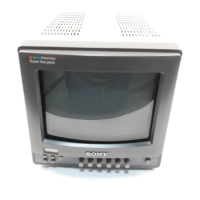
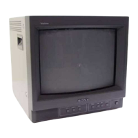
This document describes the Sony Trinitron Color Video Monitor, a professional-grade display unit designed for various video monitoring applications. The monitor is available in several models, including the PVM-14M4U/14M4E (14-inch monitor), PVM-14M2U/14M2E (14-inch monitor), PVM-20M4U/20M4E (20-inch monitor), and PVM-20M2U/20M2E (20-inch monitor). The illustrations in this manual primarily refer to the PVM-20M4U/20M4E models.
Function Description
The Trinitron Color Video Monitor is equipped with a high-resolution Trinitron picture tube, offering excellent image quality. The HR (High Resolution) Trinitron tube, found in models like the PVM-14M4U/14M4E/20M4U/20M4E, delivers a horizontal resolution of more than 800 TV lines at the center of the picture. Other models, such as the PVM-14M2U/14M2E/20M2U/20M2E, feature a Trinitron tube with a horizontal resolution of more than 600 TV lines.
A key feature is the Comb filter, which activates when NTSC video signals are received. This filter enhances Y/C separation, reducing resolution decrease, cross color, and cross luminance phenomena, thereby improving overall video quality. The Beam current feedback circuit ensures stable white balance, contributing to consistent color reproduction.
The monitor supports four color systems: NTSC, PAL, SECAM, and NTSC4.43 signals, with automatic selection of the appropriate color system. The NTSC4.43 system refers to an NTSC color system where the subcarrier frequency is modified to 4.43MHz, often output when playing back NTSC recorded video programs with certain VTRs.
For specialized viewing, the Blue only mode allows the display of an apparent monochrome picture with all three cathodes driven by a blue signal. This mode is particularly useful for adjusting color saturation and phase, as well as observing VCR noise.
The monitor offers versatile input options:
- Analog RGB/component input connectors allow for the input of analog RGB or component (Y, R-Y, B-Y) signals from various video equipment.
- Y/C input connectors facilitate the input of video signals split into chrominance (C) and luminance (Y) components. This separation eliminates interference between the two signals, which is common in composite video, ensuring higher video quality.
- External sync input enables the monitor to operate on a sync signal supplied from an external sync generator when the EXT SYNC selector is in the "on" position.
- Automatic termination is a convenient feature for connectors marked with a "W". The input connector is automatically terminated at 75 ohms internally when no cable is connected to the loop-through output connector. When a cable is connected to an output connector, this termination is automatically released.
Usage Features
The monitor includes several operational modes and settings:
- Underscan mode allows monitoring of the signal normally scanned outside the screen. Note that dark RGB scanning lines may appear at the top edge of the screen in this mode, caused by an internal test signal.
- Horizontal/vertical delay mode enables simultaneous checking of horizontal and vertical sync signals. The horizontal sync signal is displayed in the left quarter, and the vertical sync signal near the center of the screen.
- Auto/manual degaussing provides flexibility in demagnetizing the screen. Degaussing can occur automatically when the power is turned on, or manually by pressing the DEGAUSS button.
- On-screen menus offer a user-friendly interface for adjusting various settings, including color temperature, CHROMA SET UP, and other parameters.
- Five menu languages are available, allowing users to select their preferred language for the on-screen menus.
- EIA standard 19-inch rack mounting is supported with optional mounting brackets (MB-502B for 14-inch monitors) or slide rails (SLR-103A for 20-inch monitors), making it suitable for professional rack installations.
- SDI (Serial Digital Interface) Kit compatibility (with optional BKM-101C for video and BKM-102 for audio) allows the monitor to display SMPTE 259M 4:2:2 serial digital signals from digital VCRs. A connecting harness may be required for BKM-101C units with serial numbers less than 2,010,000.
- Serial Remote Interface Kit (optional BKM-103) enables remote control of the monitor from personal computers via an RS-422A serial interface.
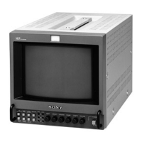
Front Panel Controls
The front panel provides intuitive controls for operation:
- Tally lamp: Lights up when the connected video camera is selected and recording.
- POWER switch and indicator: Turns the monitor on/off, with a green indicator light.
- REMOTE indicator: Lights up when "ON" is selected on the USER PRESET menu or when a remote cable is connected, disabling front panel controls.
- VOLUME control: Adjusts audio output level.
- CONTRAST control: Adjusts picture contrast.
- PHASE control: Effective for NTSC and NTSC4.43 color systems, adjusts skin tones (greenish/purplish).
- CHROMA control: Increases/decreases color intensity.
- BRIGHT (brightness) control: Increases/decreases picture brightness.
- APERTURE control: Increases/decreases sharpness.
- MENU (EXIT) button: Displays the main menu and navigates back to previous menus.
- ENTER (SELECT) button: Confirms selected menu items.
- ↑(+)/(-) buttons: Moves the cursor or adjusts selected values in menus.
- 16:9 selector: Monitors 16:9 picture signals.
- H/V DELAY selector: Observes horizontal and vertical sync signals.
- UNDER SCAN selector: Activates underscan mode.
- BLUE ONLY selector/RESET button: Eliminates red and green signals for blue-only viewing, or resets menu settings.
- DEGAUSS button: Manually demagnetizes the screen.
- EXT SYNC (external sync) selector: Toggles between internal and external sync signals.
- LINE/RGB input selector: Selects input from LINE A, B, C or RGB/COMPONENT connectors.
- C/SDI selector: Selects input from LINE C or SDI (with optional kits).
- B/COMPONENT selector: Selects input from LINE B or component signals.
- A/RGB selector: Selects input from LINE A or RGB signals.
Rear Panel Connectors
The rear panel houses various input and output connectors:
- AC IN socket: For connecting the supplied AC power cord.
- LINE A, LINE B connectors: Groups of composite video and audio input/loop-through output connectors.
- VIDEO IN (BNC): Connects to video output of equipment like VCRs or cameras.
- VIDEO OUT (BNC): Loop-through output of VIDEO IN, with automatic 75-ohm termination release.
- AUDIO IN (phono jack): Connects to audio output of VCRs or microphone amplifiers.
- AUDIO OUT (phono jack): Loop-through output of AUDIO IN.
- LINE C connectors (Y/C IN, Y/C OUT): 4-pin mini-DIN for Y/C separate video signals, with loop-through and automatic 75-ohm termination release.
- REMOTE Connector (20-pin): Connects to tally output of control consoles or remote control units.
- RGB/COMPONENT connectors (R/R-Y IN, G/Y IN, B/B-Y IN, R/R-Y OUT, G/Y OUT, B/B-Y OUT): BNC connectors for RGB or component signals, with loop-through and automatic 75-ohm termination release.
- EXT SYNC (external sync) connectors (IN, OUT): BNC connectors for external sync signals, with loop-through and automatic 75-ohm termination release.
Maintenance Features
- Cleaning: The unit should be periodically cleaned with a mild detergent solution. Strong solvents, thinners, benzine, or abrasive cleansers should be avoided as they can damage the cabinet. Always unplug the unit before cleaning.
- Repacking: Retain the original carton and packing materials for safe transport of the unit if it needs to be moved.
- Safety: Always operate the unit with the specified power source. If any solid object or liquid falls into the cabinet, unplug the unit and have it checked by qualified personnel. Do not use a damaged power cord. Unplug the unit from the wall outlet if not in use for several days. Disconnect the power cord by grasping the plug, not the cord. The socket-outlet should be installed near the equipment and be easily accessible.
- Installation: Ensure adequate air circulation to prevent heat buildup. Avoid placing the unit on surfaces that block ventilation holes or near heat sources. Protect the unit from direct sunlight, excessive dust, mechanical vibration, or shock.
- Rack Installation: When installed in a rack, ensure the operating ambient temperature does not exceed the manufacturer's maximum rated ambient temperature. Maintain adequate airflow and ensure stable mechanical loading. Consider the power supply circuit to avoid overloading and ensure reliable earthing, especially when using power strips.