Do you have a question about the Sony WALKMAN WM-702 and is the answer not in the manual?
Detailed technical specifications for the WM-702/F702.
Procedures for checking FF/REW and PLAY modes.
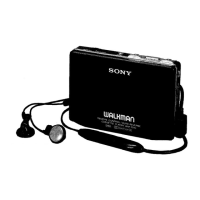
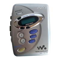
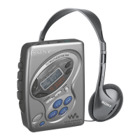
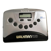
Identifies and describes unit controls and indicators.
Critical safety warnings for battery and headphones.
Procedures for mechanical adjustments like torque and tension.
Procedures for electrical adjustments and test tape usage.
Adjustments for AM tuning voltage and tracking.
Procedures for FM tuning voltage, VCO, and tracking.
Procedures for TV tuning voltage and tracking.
Lead layouts for semiconductors in the cassette section.
Location of semiconductors on the cassette PCB.
Printed wiring layout for the audio board.
Printed wiring layout for the system control board.
Printed wiring layout for the system control board (side A).
Printed wiring layout for the audio board (side A).
Block diagrams for integrated circuits (ICs).
Location of semiconductors on the radio PCB.
Common diagrams for switches and displays.
Schematic diagrams for FM, TV, and AM sections.
Exploded view and parts list for WM-F702.
Exploded view and parts list for WM-702.
List of parts for the first exploded view.
List of parts for the second exploded view.
List of parts for Mechanism Section-1.
List of parts for Mechanism Section-2.
Lists of capacitors, resistors, and semiconductors.
Continued lists of capacitors and semiconductors.
Lists of diodes, filters, coils, and transistors.
Continued lists of transistors and resistors.
Continued list of resistors.
Lists of miscellaneous components and accessories.
Block diagram for the radio section.
Terminal information for integrated circuits.
Block diagram for the cassette section.
Block diagrams for FM/TV VCO and band switch.
Block diagrams for radio control and system.
Corrections to specific pages of the service manual.
Detailed terminal functions for IC701.
Summary of input/output signals for IC701.
Details on IC701 signals and operational notes.
Table showing IC701 switch inputs and states.
Block diagrams for headphone amp, DDC, motor, servo, and system.
| Type | Cassette Player |
|---|---|
| Brand | Sony |
| Model | WALKMAN WM-702 |
| Release Year | 1989 |
| Headphone Jack | 3.5mm |
| Dolby Noise Reduction | Dolby B |
| Auto Reverse | Yes |
| Power Source | 2 x AA batteries |
| Remote Control | Yes (wired) |
| Frequency Response | 40Hz - 12kHz |
| Signal-to-Noise Ratio | 50dB |
| Wow and Flutter | 0.15% (WRMS) |