Do you have a question about the Sony WALKMAN WM-F702 and is the answer not in the manual?
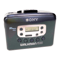
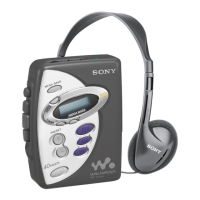
| Type | Cassette Player |
|---|---|
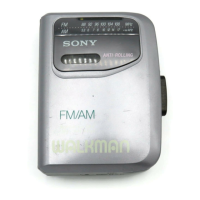
| Tuner | FM/AM |
| Power Supply | 2 x AA batteries |
| Voltage | 3V |
| Special Features | Auto-reverse |
Procedures for testing FF/REW function using square wave signal.
Procedures for testing PLAY mode using square wave signal.
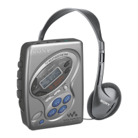
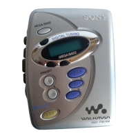
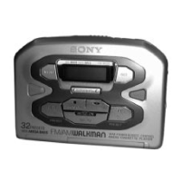
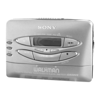
Identifies and describes the unit's buttons, switches, and indicators.
Procedures for torque and tension measurements and adjustments.
Procedures for tape speed, playback head azimuth, and level adjustments.
Shows lead pin configurations for various semiconductors.
Illustrates the physical layout of the cassette section's printed circuit boards.
Provides the detailed circuit diagram for the cassette section.
Visual representation of the internal logic and functions of key integrated circuits.
Illustrates the physical layout of the radio section's printed circuit boards.
Provides the detailed circuit diagram for the radio section.
Block diagram illustrating the radio section's signal flow and components.
Details corrections to be made in the main service manual.
Describes the function of each terminal for specific integrated circuits.
Block diagram illustrating the cassette section's signal flow and components.