EasyManua.ls Logo

Sony WM-FX1 Service Manual

Sony WM-FX1
26 pages
To Next Page IconTo Next Page
Page #1 background imageLoading...
Page #1 background image
WM-FX1
E Model
Australian Model
Tourist Model
RADIO CASSETTE PLAYER
Sony Corporation
Personal Audio Company
Published by Sony Engineering Corporation
9-959-783-12
2002A1600-1
© 2002.1
Ver 1.1 2002. 01
SERVICE MANUAL
Question and Answer IconNeed help?

Do you have a question about the Sony WM-FX1 and is the answer not in the manual?

Sony WM-FX1 Specifications

General IconGeneral
BrandSony
ModelWM-FX1
CategoryCassette Player
LanguageEnglish

Summary

Product Specifications

Radio Section

Technical details of the radio tuner.

Tape Section

Technical specifications for tape playback.

General and Battery Life

General specs, power, dimensions, and battery duration.

Section 1 General

Parts Identification

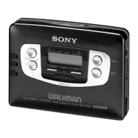
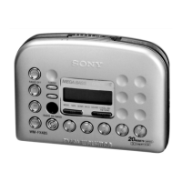
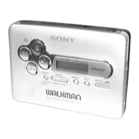
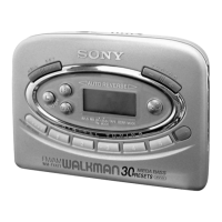
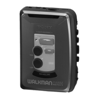
Visual identification of external components.

Section 2 Service Note

Service Mode Operation

Procedure for entering and operating the service mode.

Playback Mode Setup

Steps to set playback modes and operations.

Section 3 Disassembly

Case and Cassette Lid Disassembly

Steps to disassemble the case and cassette lid.

Tuner Unit and Reel Ornament Disassembly

Steps to disassemble tuner unit and reel ornament.

Section 4 Mechanical Adjustments

Mechanical Adjustment Precautions

Safety and preparation steps for mechanical adjustments.

Torque Measurement

Specifications and methods for torque measurement.

Section 5 Electrical Adjustments

Electrical Adjustment Precautions

Safety and preparation steps for electrical adjustments.

Tape Speed Adjustment

Procedure for adjusting tape speed.

Section 6 Diagrams

Block Diagram

Overall system block diagram.

Main Board PWB (JE Model)

Printed wiring board layout for JE model.

Section 6 Diagrams

Main Board PWB (Suffix 22)

Printed wiring board layout for suffix 22.

Section 6 Diagrams

Schematic Diagram

Circuit schematic of the device.

Section 6 Diagrams

Semiconductor Lead Layouts

Lead configurations for semiconductor components.

Section 6 Diagrams

IC Pin Functions

Pin assignments and functions for integrated circuits.

Section 6 Diagrams

IC701 System Controller Pinout

Pinout and function of IC701.

Section 7 Exploded Views

Cabinet Section Exploded View

Exploded view of the cabinet assembly.

Section 7 Exploded Views

Main Board Section Exploded View

Exploded view of the main board components.

Section 7 Exploded Views

Mechanism Section Exploded View

Exploded view of the mechanism assembly.

Section 8 Electrical Parts

ATS Flexible Board Components

List of electrical parts for the ATS flexible board.

Main Board Components

List of electrical parts for the main board.

Capacitor Component List

Detailed list of capacitors used in the device.

Section 8 Electrical Parts

Component Lists by Type

Lists of ICs, Diodes, Filters, Connectors, etc.

Section 8 Electrical Parts

Transistor Component List

List of transistors used in the device.

Resistor Component List

List of resistors used in the device.

Section 8 Electrical Parts

Metal Chip Resistors

List of metal chip resistors.

Switches and Vibrators

List of switches and vibrator components.

Section 8 Electrical Parts

Tuner Unit and Accessories

Parts list for tuner unit and accessories.

Miscellaneous Components

List of other miscellaneous parts.

Related product manuals