Do you have a question about the Sony WM-FX277 and is the answer not in the manual?
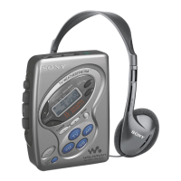
Overview of the player's buttons, switches, and controls.
Procedures for disassembling the cassette holder and front cabinet.
Steps to access main board, mechanism deck, belt, motor, and playback head.
Detailed steps for cassette holder assembly procedures.
Procedures for mechanical torque, electrical calibration, and tuner section adjustments.
Detailed list of IC terminals and their functions for system control.
System block diagram and detailed diagrams for integrated circuits.
Visual layout of components and traces on the main board's sides A and B.
Notes for schematic interpretation and illustrated waveforms for key signals.
Illustrated breakdown of cabinet parts with reference numbers and descriptions.
Illustrated breakdown of mechanism deck parts with reference numbers and descriptions.
List of capacitors, semiconductors, and resistors with part numbers and values.
List of transistors, coils, variable resistors, switches, and accessories.
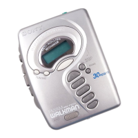
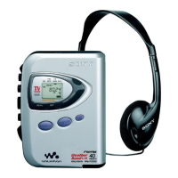
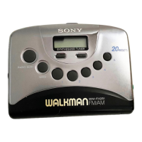
The WM-FX241 is a portable radio cassette player designed for personal audio entertainment, offering a blend of cassette playback and radio reception. This device is an "E Model," indicating specific regional configurations, and shares many similarities with the WM-FX277 (5E Model), with key differences highlighted in its parts list.
The primary function of the WM-FX241 is to provide audio playback from cassette tapes and receive radio broadcasts. It supports both FM and AM radio bands, allowing users to tune into a wide range of stations. The device is powered by two R6 (AA) batteries, emphasizing its portability and suitability for on-the-go use.
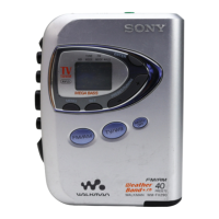
For cassette playback, the WM-FX241 features standard controls such as PLAY, STOP, FF (Fast Forward), and REW (Rewind). These controls enable users to navigate through their cassette tapes with ease. The device also incorporates a "MEGA BASS" function, which enhances the low-frequency audio output, providing a richer and more impactful sound experience, particularly beneficial for music playback.
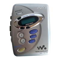
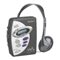
Radio reception is managed through digital tuning, offering precise station selection. Users can adjust the tuning using dedicated +/- buttons and store preferred stations as presets. The device includes a "DX/LOCAL" switch, which allows users to optimize radio reception based on their location, either for distant (DX) or local signals. An "ST FM MONO" switch is also available, likely to improve reception clarity in areas with weak FM stereo signals by switching to monaural output.
Audio output is primarily through stereo headphones or earphones, which are typically supplied with the device. A volume control allows users to adjust the listening level. Additionally, the WM-FX241 features an AVLS (Automatic Volume Limiter System) with a "NORM/LIMIT" setting. This function helps protect the user's hearing by preventing excessively high volume levels, offering a safer listening experience.
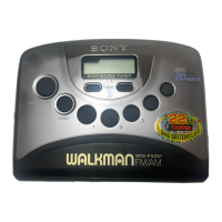
The WM-FX241 is designed for user-friendliness and portability. Its compact dimensions and lightweight construction make it easy to carry, whether in a pocket, bag, or using the supplied carrying case with a belt clip. The digital tuning interface, combined with preset capabilities, simplifies the process of finding and saving favorite radio stations. The "HOLD" function is a practical feature that prevents accidental button presses, which is particularly useful when the device is being carried or stored.
The inclusion of the "MEGA BASS" feature caters to users who prefer an enhanced bass response in their audio. This can significantly improve the enjoyment of various music genres. The AVLS system, with its selectable "NORM/LIMIT" modes, provides a thoughtful safety feature, allowing users to control their listening volume and prevent potential hearing damage from prolonged exposure to high sound levels.
The device's power source, two AA batteries, is a common and easily replaceable type, ensuring that users can maintain power even when away from charging facilities. This further underscores its design for portability and convenience. The instruction manual, provided in multiple languages (English, Spanish, Portuguese), ensures that a broad range of users can understand and operate the device effectively.
Maintenance of the WM-FX241 involves several key aspects to ensure its longevity and optimal performance. For mechanical adjustments, it is crucial to clean specific parts with a denatured-alcohol-moistened swab. These parts include the playback head, capstan, pinch roller, and rubber belt. Regular cleaning of these components helps prevent audio quality degradation and mechanical issues caused by dust and tape residue.
Demagnetizing the playback head with a head demagnetizer is also recommended. This process removes residual magnetism that can build up over time and affect sound quality. Users are cautioned against using a magnetized screwdriver for adjustments, as this could inadvertently magnetize the playback head.
When performing torque measurements, the device should be operated with a rated power supply voltage of 2.5V, unless otherwise specified. This ensures accurate readings for tape playback (FWD) and fast forward/rewind (FF, REW) functions, as well as back tension.
For electrical adjustments, the tape speed can be adjusted by accessing the RV601 component. This involves carefully removing seven claws on the Window (LCD) to expose the adjustment screw. Users are advised to use a precision screwdriver, covering the tip with a cloth to prevent damage to the claws or the LCD window. The tape speed adjustment procedure involves playing a WS-48A test tape (3kHz, 0dB) and adjusting RV601 until the frequency counter reads 3,000Hz (with a standard value range of 2,985-3,015Hz). After initial adjustment, the tape should be checked at the top and end to ensure the reading remains within ±1.0% of the initial setting.
Tuner section adjustments for both AM and FM bands are also outlined. These involve adjusting various components like T1, L4, L1, CT1, L3, and L2 to optimize frequency coverage and tracking. For AM IF adjustment, T1 is adjusted for maximum reading on a level meter at 1400kHz. AM frequency coverage involves adjusting L4 for a specific voltage reading on a digital voltmeter at 530kHz. AM tracking requires adjusting L1 and CT1 for maximum level meter readings at 620kHz and 1400kHz, respectively. Similarly, FM frequency coverage involves adjusting L3 for a specific voltage reading at 108MHz, and FM tracking requires adjusting L2 at 98MHz and 108MHz. These adjustments are critical for ensuring clear and accurate radio reception.
Flexible circuit board repair requires careful handling, maintaining a soldering iron temperature around 270°C and avoiding repeated contact with the same conductor. When replacing chip components, it's important not to reuse disconnected parts and to be mindful of heat damage to tantalum capacitors.
The exploded views and parts lists provided in the manual are essential resources for identifying and replacing components during repair. These diagrams detail the cabinet section and mechanism deck, including parts like the cassette holder, main board, belt, capstan/reel motor, and magnetic head. The detailed breakdown of parts, along with their descriptions and part numbers, facilitates accurate and efficient servicing of the device.
| Type | Cassette Player |
|---|---|
| Brand | Sony |
| Model | WM-FX277 |
| Media Type | Cassette |
| Power Source | 2 x AA Batteries |
| Mega Bass | Yes |
| Recording Function | No |
| Auto Reverse | Yes |
| Radio Tuner | AM/FM |
| Playback Function | Play, Stop |
| Headphones | 3.5 mm Stereo Jack |