EasyManua.ls Logo

Sony WM-FX267 User Manual

Sony WM-FX267
26 pages
To Next Page IconTo Next Page
Page #1 background imageLoading...
Page #1 background image
MICROFILM
SERVICE MANUAL
RADIO CASSETTE PLAYER
US Model
WM-FX267/FX269
AEP Model
E Model
WM-FX267
Model Name Using Similar Mechanism WM-FX251
Tape Transport Mechanism Type MF-WMFX251-114
Frequency range
FM: 87.5-108MHz
AM: 530-1710kHz (US)
AM: 531-1602kHz (EXCEPT US)
Power requirements
3V DC batteries AA (R6) × 2/External DC 3V
power sources
Demensions
115 × 90.5 × 34.4mm (4
5
/8 × 3
5
/8 1
3
/8 inches) (w/h/d)
incl. projecting parts and controls
• Mass
Approx. 150g (5.3 oz)
Approx. 230g (8.2 oz) incl. batteries and a tape
• Supplied accessories
Stereo headphones or earphones (1)
Carrying case (1)
Design and specifications are subject to change without notice.
SPECIFICATIONS
WM-FX267/FX269
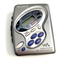
Photo: WM-FX267 US model
Ver 1.3 2000. 05
With SUPPLEMENT-1
(9-923-300-81)
With SUPPLEMENT-2
(9-923-300-82)
Question and Answer IconNeed help?

Do you have a question about the Sony WM-FX267 and is the answer not in the manual?

Sony WM-FX267 Specifications

General IconGeneral
BrandSony
ModelWM-FX267
CategoryCassette Player
LanguageEnglish

Summary

General Information and Operation

Location of Parts and Controls

Overview of device controls and their functions.

Playing a Tape

Instructions for inserting and playing cassette tapes.

Listening to the Radio

Steps for tuning into radio stations and improving reception.

Precautions and Safety

Important warnings and safety guidelines for operating the device.

Disassembly Procedures

Cabinet and Front Assembly

Procedure for removing the front cabinet and related parts.

Main Board and Mechanism Deck Removal

Steps to detach the main circuit board and tape transport mechanism.

Belt and Motor Replacement

Guide for accessing and replacing the drive belt and motor.

Mechanical Adjustments

Torque Measurement

Specifications and methods for measuring torque for tape transport.

Electrical Adjustments

Servicing Precautions

Guidelines for voltage, switch positions, and control settings during adjustments.

Tape Section Adjustments

Procedures for adjusting tape playback speed and performance.

Tuner Section Adjustments

Calibration steps for FM and AM radio tuning and signal tracking.

Diagrams and Schematics

IC Pin Function Description

Detailed pin assignments and functions for integrated circuits.

Block Diagram

High-level overview of the device's internal signal paths and components.

Schematic Diagram

Detailed electrical circuit schematics for the device.

Exploded Views

Main Section 1

Exploded view of the primary internal components, including the main section.

Main Section 2

Exploded view of the secondary internal components, including the main board.

Mechanism Deck Section

Exploded view of the tape transport mechanism and its parts.

Electrical Parts List

Main Components

List of main electronic components, including capacitors, resistors, and ICs.

Semiconductor Components

List of semiconductor components like transistors and diodes used in the circuit.

Resistors and Variable Resistors

List of resistance components, including fixed and variable resistors.

Switches and Accessories

List of switches, transformers, thermistors, and accessories.

Related product manuals