EasyManua.ls Logo

Sony WM-FX271 Service Manual

Sony WM-FX271
27 pages
To Next Page IconTo Next Page
Page #1 background imageLoading...
Page #1 background image
– 1 –
MICROFILM
SERVICE MANUAL
US Model
WM-FX271/FX275
Canadian Model
AEP Model
E Model
Chinese Model
WM-FX271
WM-FX271/FX275
RADIO CASSETTE PLAYER
Photo: WM-FX271
Frequency range
FM: 65 – 74/87.5 – 108 MHz (East European)
87.5 – 108 MHz (Except East European)
AM:530 – 1,710 kHz (US, Canadian)
531 – 1,602 kHz (Except US, Canadian)
Power requirements
3 V DC batteries R6 (AA) × 2/External DC 3 V power sources
Dimensions
91.4 × 115.5 × 35.9 mm (3 5/8 × 4 5/8 × 1 7/16 inches) (w/h/d) incl.
projecting parts and controls
Mass
Approx. 150 g (5.3 oz.)
Approx. 230 g (8.2 oz.) incl.batteries and a tape
Supplied accessories
Stereo headphones or Stereo earphones (1)/Carrying case (1)
Design and specifications are subject to change without
notice.
SPECIFICATIONS
Model Name Using Similar Mechanism WM-FX171
Tape Transport Mechanism Type MF-WMFX171-114
Flexible Circuit Board Repairing
Keep the temperature of the soldering iron around 270˚C during
repairing.
Do not touch the soldering iron on the same conductor of the
circuit board (within 3 times).
Be careful not to apply force on the conductor when soldering
or unsoldering.
Notes on Chip Component Replacement
Never reuse a disconnected chip component.
Notice that the minus side of a tantalum capacitor may be dam-
aged by heat.
Ver 1.0 1999. 02
Question and Answer IconNeed help?

Do you have a question about the Sony WM-FX271 and is the answer not in the manual?

Sony WM-FX271 Specifications

General IconGeneral
BrandSony
ModelWM-FX271
CategoryCassette Player
LanguageEnglish

Summary

SPECIFICATIONS

Power Requirements

Specifies the power sources, including battery type and external DC input.

SECTION 1 GENERAL

Location of Parts and Controls

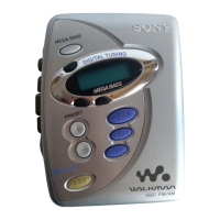
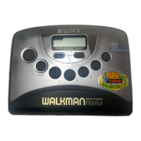
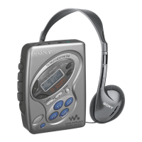
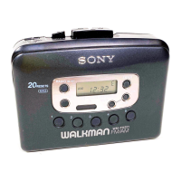
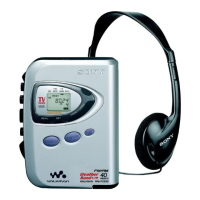
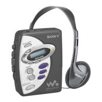
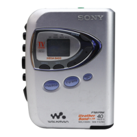
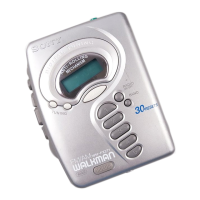
Identifies and labels the external buttons, switches, and displays on the device.

SECTION 2 DISASSEMBLY

SECTION 4 ELECTRICAL ADJUSTMENTS

Tape Speed Adjustment Procedure

Steps to adjust the tape playback speed using a frequency counter.

SECTION 5 DIAGRAMS

IC Pin Description

Details the function of each pin for the main system control IC.

Block Diagram

Illustrates the overall signal flow and component interconnections.

Printed Wiring Board

Shows the physical layout of components and traces on the main circuit board.

Schematic Diagram

Provides the detailed electronic circuit schematic for the device.

SECTION 6 EXPLODED VIEWS

IC Block Diagrams

Functional block diagrams for key integrated circuits used in the device.

Related product manuals