Do you have a question about the Sony WM-FX251 and is the answer not in the manual?
Instructions for replacing ceramic filters (CF2, X2) with correct types.
Guidelines for soldering and handling flexible circuit boards during repair.
Important notes on reusing or damaging chip components during replacement.
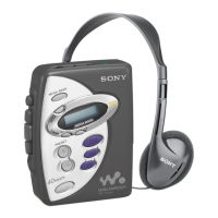
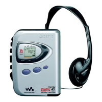
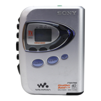
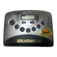
Identifies the location and function of external buttons and indicators.
Key safety warnings and guidelines for operating the device.
Instructions for inserting batteries and handling battery leakage.
Guidance on using external power sources and the carrying case.
Step-by-step guide to remove the front cabinet assembly.
Instructions for detaching the main circuit board from the chassis.
Procedure for removing the cassette lid mechanism.
Details on removing the mechanism deck and its motor.
Safety notes and torque measurement for mechanical adjustments.
Adjustments specific to the tape transport mechanism.
Important precautions and control settings for electrical adjustments.
Tuning procedures for tape, tuner, FM, and AM sections.
Detailed pinout and function for integrated circuits.
Visual representation of component placement on the PCB.
Detailed electronic circuit schematics for the device.
Illustrates key signal waveforms and provides notes on schematic interpretation.
High-level block diagrams of integrated circuit functions.
Identifies components in the main section, part 1.
Identifies components in the main section, part 2.
Identifies components in the mechanism section, part 1.
List of capacitors with part numbers, values, and specifications.
Part numbers for filters, connectors, trimmers, and diodes.
Part numbers for ICs, jacks, and jumper resistors.
Part numbers for coils, displays, and transistors.
List of resistors with part numbers, values, and specifications.
Part numbers for variable resistors and switches.
Part numbers for transformers, thermistors, and vibrators.
Part numbers for miscellaneous items and accessories.
Guide to identify motor types based on screw hole configuration.
Guide to identify different main board versions.
| Brand | Sony |
|---|---|
| Model | WM-FX251 |
| Category | Cassette Player |
| Language | English |