EasyManua.ls Logo

Sony WM-FX193 Service Manual

Sony WM-FX193
18 pages
To Next Page IconTo Next Page
Page #1 background imageLoading...
Page #1 background image
Ver 1.0 2000.01
MICROFILM
WM-FX193/FX195
RADIO CASSETTE PLAYER
SPECIFICATIONS
US Model
WM-FX193
Canadian Model
AEP Model
E Model
Chinese Model
WM-FX193/FX195
Model Name Using Similar Mechanism NEW
Tape Transport Mechanism Type MF-WMFX195-114
Photo : WM-FX195
Frequency range
FM: 87.5 - 108 MHz (Italy, Saudi Arabia)
87.6 - 107.9 MHz (Other countries)
AM: 526.5 - 1606.5 kHz (Italy, Saudi Arabia))
531 - 1602 kHz (Other countries)
Power requirement
3 V DC batteries R6 (AA) x 2
Dimensions
89.1 x 117.7 x 35.5 mm (w/h/d) incl. projecting parts and
controls
Mass
Approx. 140 g/Approx. 220 g incl. batteries and a cassette
Supplied accessories
Stereo headphones or Stereo earphones (1)/Belt clip (1)
Design and specifications are subject to change without notice.
Battery life (approximate hours) (EIAJ*)
Sony alkaline LR6 (SG) Sony R6P (SR)
playback 25 7.5
radio 55 18
* Measured value by the standard of EIAJ (Electronic
Industries Association of Japan). (Using a Sony HF series
cassette tape)
Note
• The battery life may shorten depending on the operation of
the unit.
SERVICE MANUAL
Question and Answer IconNeed help?

Do you have a question about the Sony WM-FX193 and is the answer not in the manual?

Sony WM-FX193 Specifications

General IconGeneral
TypeCassette Player
BrandSony
ModelWM-FX193
TunerFM/AM
Power Source2 x AA batteries
Mega BassYes
Wow and Flutter0.15%
Weight190 g (without batteries)

Summary

SECTION 1 GENERAL

Location and Function of Controls

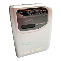
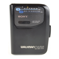
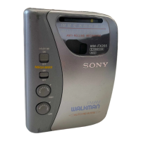
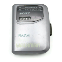
Identifies and describes the functions of the player's controls and indicators.

SECTION 2 DISASSEMBLY

Cabinet (Rear) Sub ASSY

Procedure for disassembling the rear cabinet sub-assembly.

Main Board

Steps for accessing and removing the main circuit board.

Mechanism Deck

Instructions for removing the tape mechanism deck.

Belt, Capstan/Reel Motor (M901)

Details on replacing the drive belt and motor.

Holder Sub ASSY, Cassette

Procedure for disassembling the cassette holder assembly.

SECTION 3 ADJUSTMENTS

Mechanical Adjustments

Procedures for cleaning and adjusting mechanical parts like the head and pinch roller.

Electrical Adjustments

Guides for setting tape speed and tuning adjustments for optimal performance.

SECTION 4 DIAGRAMS

Block Diagram

Illustrates the overall functional blocks and signal flow of the device.

Printed Wiring Boards

Shows the component layout on the printed circuit boards for reference.

SECTION 5 EXPLODED VIEWS

Cabinet Section

Exploded view of the outer casing and related parts.

Mechanism Section-1

Exploded view of the primary mechanical components of the tape mechanism.

Mechanism Section-2

Exploded view of secondary mechanical parts and gears within the mechanism.

SECTION 6 ELECTRICAL PARTS LIST

MISCELLANEOUS

Accessories & Packing Materials

Details on included accessories, replacement parts, and instruction manuals for the device.

Related product manuals