EasyManua.ls Logo

Sony WM-FX12

Sony WM-FX12
14 pages
To Next Page IconTo Next Page
Loading...
Snape
-
4)
ee
tee
pe
ee
a
a
eae
rm
i
ee
nnn
I
TT
nro
MEME
ET
Seto
SERVICE
MANUAL
RASC
cee
Benen
PvP
do
sf
ore
sy
fe
DESPRE.
US
Model
Canadian
Mode!
AEP
Model!
UK
Mode!
E
Mode!
Pa
SPECIFICATIONS
Radio
|
FM:
87.6—108MHz
(US,
Canadian
models)
87.6—107MHz
(Germany
mode!)
87.5—108MHz
(Italian
model)
87.6—107.9MHz
(Other
countries
modeis)
AM:
530—1,710kHz
(US,
Canadian
models)
526.5
—1,606.5
kHz
(itatian
modet)
§31—1,602kHz
(Other
countries
models)
3
V
DC
batteries
R6
(AA)
x
2
2
External
DC
3
V
power
sources
Battery
life
(Approximate
hours)
Power
requirements
|
|
Sony
Alkaline
AM3
(N)
8
hrs.
30
hrs.
Sony
SUM-3
(NS)
Rechargeable
Battery
|
(US,
Canadian
models)
2.5
hrs.
Accessories
supplied
Stereo
headphones
(1)
Beitclip
(1)
-
Battery
charger
(1)
(US,
Canadian
modeis)
Rechargeable
batteries
(2}
(US,
Canadian
models)
Your
dealer
may
not
handle
some
of
the
above
listed
accessories.
Please
ask
the
dealer
for
detailed
information.
|
=
|
Design
and
specifications
subject
to
change
without
notice.
MICROFILM:
WM-F
X10
MT-WMEX10-48
MT-WMEX10M-48
FLEXIBLE
CIRCUIT
BOARD
REPAIRING
@
Keep
the
temperature
of
the
soldering
iron
around
270°C
during
repairing.
|
|
®
Do
not
touch
the
soldering
iron
on
the
same
conductor
of
the
circuit
board
(within
3
times).
e
Be
careful
not
to
apply
force
on
the
conductor
when
soldering
or
unsoldering.
a
NOTES
ON
CHIP
COMPONENT
REPLACEMENT
®
Never
reuse
a
disconnected
chip
component.
@
Notice
that
the
minus
side
of
a
tantalum
capacitor
may
be
damaged
by
heat.
|
|
i
RADIO
CASSETTE
PLAYER
SONY.
Question and Answer IconNeed help?

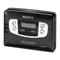
Do you have a question about the Sony WM-FX12 and is the answer not in the manual?

Sony WM-FX12 Specifications

General IconGeneral
BrandSony
ModelWM-FX12
CategoryCassette Player
LanguageEnglish

Summary

SPECIFICATIONS

Radio and Power Specifications

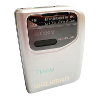
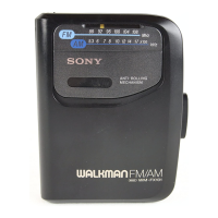
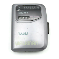
Details FM/AM frequency bands, power requirements, and battery life.

Repair and Component Handling Notes

Flexible Circuit Board Repair Guidelines

Advice on soldering temperatures and techniques for flexible circuits.

Chip Component Replacement Precautions

Guidelines for handling and replacing chip components, especially tantalum capacitors.

SECTION 1 DISASSEMBLY

Rear Cabinet Disassembly Procedure

Step-by-step guide for removing the rear cabinet assembly.

Mechanism and Main Board Removal

Instructions for detaching the mechanism deck and main board.

Component Assembly Details

Main Board Removal Steps

Illustrates the process of disassembling the main board.

Cassette Lid Assembly Disassembly

Shows the steps required to remove the cassette lid.

Dial Pointer Setting Procedure

Pointer Adjustment Guide

Detailed instructions for correctly setting the dial pointer.

SECTION 2 ADJUSTMENTS

Mechanical Adjustment Procedures

Covers cleaning, demagnetizing, and torque measurements.

Electrical Adjustment Settings

Details voltage supply, switch positions, and control settings.

Tape Speed Calibration

Instructions for adjusting and verifying tape playback speed.

Radio Section Tuning and Alignment

FM Frequency Coverage Adjustment

Procedure for tuning FM frequency reception range.

FM Tracking Adjustment

Steps for calibrating FM signal tracking across frequencies.

AM Section Alignment and Coverage

Instructions for AM IF alignment and frequency coverage adjustments.

SECTION 3 DIAGRAMS

System Block Diagram

Provides a high-level overview of the device's functional blocks.

Component Identification and Notes

Semiconductor Location Mapping

Lists semiconductor components and their positions.

Schematic Diagram Conventions

Explains symbols, notations, and abbreviations used in schematics.

Schematic Diagram Details

Main Board Circuit Schematic

Presents the detailed electrical schematic for the main board.

SECTION 4 EXPLODED VIEWS

Main Section Exploded Parts View

Illustrates the assembly of the primary physical components.

Mechanism Section Exploded Parts View

Shows a detailed breakdown of the tape mechanism parts.

SECTION 5 ELECTRICAL PARTS LIST

Capacitor Component Details

Lists all capacitor parts, their values, and specifications.

Resistor and Semiconductor Parts

Lists resistor and semiconductor components with their values.

Detailed Component Listings

Coils, Filters, Connectors, and Diodes

Lists passive components, connectors, and diodes.

Integrated Circuits (ICs) and Jacks

Details integrated circuits and external connection jacks.

Transistors and Resistors

Provides specifications for transistors and additional resistors.

Miscellaneous Items and Documentation

Accessory and Packing Materials

Lists included accessories and packing materials.

Manuals and Safety Information

Details available manuals and safety instructions.

Related product manuals