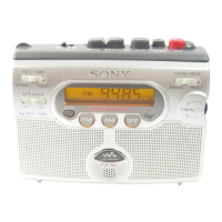
WM-GX400
77
SECTION 4
DIAGRAMS
Pin No. Pin name I/O Description
1 XOUT O Connected to 75kHz Crystal oscillator
2 TEST2 I For Test
3 – 6 PA3 – 0 I Control key inputs
7 RADIO ON O Radio on/off control signal output
8, 9 PB2, 1 O Key source signal outputs
10 MOTOR BRK O Motor brake control signal output
11 PUSH I Tuning dial (S701) common switch signal input
12 PAUSE I Pause switch (S303) signal input
13 VERSION I Destination select signal input
14 BAND O Band select signal output
15 SD I SD input
16 COMP I COMP input
17 TU MODE I Tuning mode select switch (S707) signal input
18 TUNING-A I Tuning dial (S701) A switch signal input
19 AMP ON O Power amplifier on/off control signal output
20 BEEP O Beep signal output
21 BACK UP I Back-up voltage detection signal input
22 BATT I Battery voltage detection signal input
23 FACTORY — Not used Pull-up
24 VSS — Power supply ground terminal
25 MUTE O Mute signal output
26 MOTOR CTL O Motor control signal output
27 N/R SW O N/R switch signal output
28 REC I REC detection signal input
29 TAPE I Tape on/off detection signal input
30 X2 I Tape speed select switch (S706) signal input
31 TUNING-B I Tuning dial (S701) B switch signal input
32 PRE CTL — Not used
33 – 44 S12 – S1 O LCD driver segment output terminal
45 – 48 COM4 – 1 O LCD driver common output terminal
49 – 52 DBR4 – 1 I For LCD power supply booster
53 XRESET I System reset signal input
54 TU O Output for tuning voltage generator
55 VDD — Power supply terminal
56 FM IN I FM VCO input
57 AM IN I AM VCO input
58 VSS — Power supply ground terminal
59 E0 O Main charge pump output
60 AIN I LPF amplifier input
61 AOUT O LPF amplifier output
62 AGND — LPF amplifier ground
63 TEST1 I For test
64 XIN I Connected to 75kHz Crystal oscillator
4-1. EXPLANATION OF IC TERMINALS
IC701 (SYSTEM CONTROL/LCD DRIVE) LC72349W-9A27
TUNER SECTION 0 dB = 1 µV
AM Section
FUNCTION switch: AM
FM Section
FUNCTION switch: FM
• Repeat the procedures in each adjustment several times, and the
frequency coverage and tracking adjustments should be finally
done by the trimmer capacitors.
AM IF ADJUSTMENT
Adjust for a maximum reading on level meter.
RV2 999 kHz <1,000kHz>
AM TRACKING ADJUSTMENT
Adjust for a maximum reading on level meter.
L7 621 kHz <620kHz>
CT1 1,404 kHz <1,400kHz>
FM TRACKING ADJUSTMENT
Adjust for a maximum reading on level meter.
L4 96.0 MHz
FM VCO Adjustment
Procedure:
1. Connect the resistor 10kΩ between TP1 and TP332.
2. Connect the frequency counter to TP1 (IC1 7 pin).
3. Set FUNCTION switch to FM.
4. Tune the set in 96MHz.
5. Adjust RV1 so that the reading on the frequency counter be-
comes 76 kHz.
Specifications: 75 kHz - 77 kHz
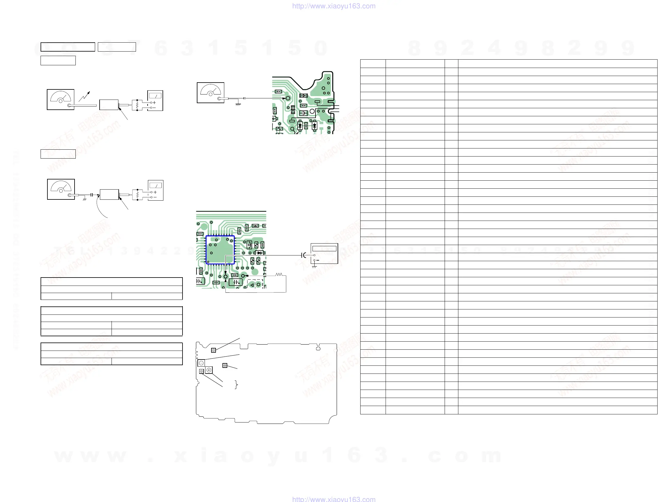
AM RF SSG
set
30% amplitude modulation by
400Hz signal.
Output level : as low as possible
Put the lead-wire
antenna close to
the set.
16
Ω
i
headphone jack (J301
level meter
FM RF SSG
set
30% amplitude
modulation by
1kHz signal.
Deviation :
±
75kHz
Output level : as low
as possible
0.01
µ
F
16
Ω
i
headphone jack (J301
main board
TP2
level meter
(side B)
3
C15
D4
C28
FB201
FB101
D2
FB301
R15
TP2
47
C3
TP368
TP369
TP370
0.01
µ
F
FM RF SSG
TP2
(ANT)
Carrier frequency : 96MHz
Deviation : none
Output level : 562
µ
V (55dB)
[MAIN BOARD] (SIDE B)
Adjustment Location:
[MAIN BOARD] (SIDE B)
IC1
C1
D
C28
L6
L2
C10
C8
12
C9
C20
C21
C18
R18
R20
R17
TP1
1
10
11
20
21
30
31
40
TP333
C34
TP331
TP332
-4
+
+
10k
Ω
TP1
(IC1
7
pin)
1
µ
F
frequency
counter
[MAIN BOARD] (SIDE B)
L7:
CT1:
RV2: AM IF Adjustment
L4: FM Tracking Adjustment
RV1: FM VCO Adjustment
AM Tracking Adjustment
no mark : 9kHz step
< > : 10kHz step
w
w
w
.
x
i
a
o
y
u
1
6
3
.
c
o
m
Q
Q
3
7
6
3
1
5
1
5
0
9
9
2
8
9
4
2
9
8
T
E
L
1
3
9
4
2
2
9
6
5
1
3
9
9
2
8
9
4
2
9
8
0
5
1
5
1
3
6
7
3
Q
Q
TEL 13942296513 QQ 376315150 892498299
TEL 13942296513 QQ 376315150 892498299
http://www.xiaoyu163.com
http://www.xiaoyu163.com
 Loading...