EasyManua.ls Logo

Sony WM-GX677 User Manual

Sony WM-GX677
28 pages
To Next Page IconTo Next Page
Page #1 background imageLoading...
Page #1 background image
WM-GX677
Tourist Model
SERVICE MANUAL
RADIO CASSETTE CORDER
MICROFILM
Model Name Using Similar Mechanism WM-GX670/GX674
Tape Transport Mechanism Type MF-WMGX670-162
SPECIFICATIONS
Manufactured under license from Dolby Laboratories
Licensing Corporation.
“DOLBY” and the double-D symbol a are trademarks
of Dolby Laboratories Licensing Corporation.
Radio section
Frequency range FM : 76.0 – 90.0 MHz
AM: 531 – 1,710 kHz
Tape section
Frequency response
(Dolby NR off) Playback: 40 – 15,000 Hz
(EIAJ) Recording/playback: 100 – 8,000 Hz
Output Headphones (2 REMOTE) jack
Load impedance 8 – 300
Input Microphone (MIC) jack
Minimum input level 0.4 mV
General
Power requirements 1.5 V
Rechargeable battery
One R6 (size AA) battery
Dimensions (w/h/d) Approx. 108.4 × 77.7 × 23.8 mm
(4
3
/8 × 3
1
/8 ×
15
/16 inches), incl.
projecting parts and controls
Mass Approx. 150 g (5.3 oz)
Approx. 215 g (7.6 oz) incl.
rechargeable battery and a cassette
Accessories Battery charger
Battery case
Stereo earphones with remote control
Carrying pouch
Rechargeable battery carring case
Stereo microphone
Instruction manual
Design and specifications are subject to change without notice
Ver 1.1 2000. 08
w
w
w
.
x
i
a
o
y
u
1
6
3
.
c
o
m
Q
Q
3
7
6
3
1
5
1
5
0
9
9
2
8
9
4
2
9
8
T
E
L
1
3
9
4
2
2
9
6
5
1
3
9
9
2
8
9
4
2
9
8
0
5
1
5
1
3
6
7
3
Q
Q
TEL 13942296513 QQ 376315150 892498299
http://www.xiaoyu163.com
Question and Answer IconNeed help?

Do you have a question about the Sony WM-GX677 and is the answer not in the manual?

Sony WM-GX677 Specifications

General IconGeneral
BrandSony
ModelWM-GX677
CategoryCassette Player
LanguageEnglish

Summary

SERVICE NOTE

GENERAL DEVICE INFORMATION

LOCATION OF CONTROLS

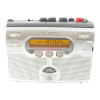
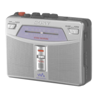
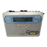
Identifies and describes the device's main controls and their functions.

REMOTE CONTROL OVERVIEW

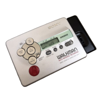
Identifies and describes the functions of the remote control unit.

DISASSEMBLY PROCEDURES

CASE BLOCK ASSEMBLY

Procedure for removing the main casing of the unit.

DRIVE BELT REPLACEMENT

Steps involved in replacing the drive belt.

CASSETTE LID DISASSEMBLY

Detailed steps for disassembling the cassette lid.

REEL ORNAMENT REMOVAL

Process for removing the reel ornament part.

MAIN BOARD REMOVAL

Instructions for removing the main circuit board.

MOTOR (M601) DISASSEMBLY

Procedure for disassembling and removing the motor.

HOLDER ASSEMBLY DISASSEMBLY

Steps for removing the holder assembly.

PINCH LEVER ASSEMBLY

Procedure for disassembling the pinch lever mechanisms.

MAGNETIC HEAD (HP901) REMOVAL

Steps for removing the magnetic head assembly.

MECHANICAL ADJUSTMENT GUIDE

ELECTRICAL ADJUSTMENT GUIDE

TECHNICAL DIAGRAMS

SYSTEM BLOCK DIAGRAM

Overall system functional block diagram.

PRINTED WIRING BOARD LAYOUT

Printed circuit board layout and component identification.

IC BLOCK DIAGRAMS

Internal block diagrams of integrated circuits.

SCHEMATIC DIAGRAM (PART 1)

Detailed electronic circuit schematic, part 1.

IC PIN FUNCTION DESCRIPTIONS

Pinout and function details for integrated circuits.

SCHEMATIC DIAGRAM (PART 2)

Detailed electronic circuit schematic, part 2.

EXPLODED VIEWS

CABINET AND MAIN BOARD EXPLODED VIEW

Exploded view of the unit casing and main board assembly.

MECHANISM DECK EXPLODED VIEW

Exploded view of the tape transport mechanism components.

ELECTRICAL PARTS LIST

Related product manuals