72
XC-ST70/ST70CE/ST50/ST50CE/ST51/ST51CE/ST30/ST30CE
Digital Video Camera
Intelligent
XCI
XC (Non-TV Format)
XC (TV Format)
Accessories
XCL XCGXCD
Color Camera Module
Color PTZ Camera
FCBEVI
Analog Video Camera
This mode provides continuous video output with the electronic
shutter selected by switches to capture a high-speed moving
object clearly.
Normal shutter speed settings
There are two shutter types: normal shutter and external trigger
shutter. Select them with the DIP switches on the rear panel.
About the Electronic Shutter
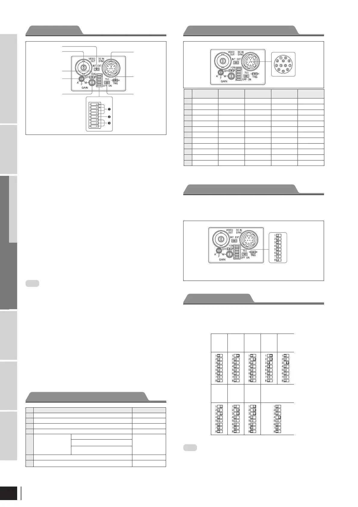
Rear panel
Switches 1 to 4: Shutter speed
Switch 5: Potential accumulation mode
Switches 6 to 8: Restart reset/External trigger shutter mode switch
* If you set the mode to ickerless, the positions of DIP switches 1 to 3 are optional.
Normal Shutter
Note
The DIP switch 5 position is optional. (The eld setting is
recommended.) The eld setting can obtain a sensitivity that is
twice that of the frame setting.
(Unit: second)
Shutter
OFF
1/125 1/250 1/500 1/1000
1/2000 1/4000 1/10000
Flickerless*
1/100 (EIA)
1/120 (CCIR)
Rear panel
Connector Pin Assignments
DIP switches
* Common ground for pins 7, 10, and 11
Rear Panel
Factory Mode Settings of Rear Panel
1) This unit is shipped from the factory with the GAIN switch being set to F ( x), so the Manual
gain control knob is not operative unless the switch setting is changed. When the GAIN switch
is set to M (manual), you can rotate this knob to adjust gain over the range 0 to 18 dB.
No. Switch
Factory setting mode
1
HD/VD signal input/output switch EXT
3
γ
compensation ON/OFF switch OFF
4
GAIN switch F
5
Manual gain control –
1)
6
Shutter speed/Mode
setting DIP switches
Shutter speed (bits 1 – 4)
OFF
(All S/W are left
side)
Potential accumulation mode (bit 5)
Restart reset/External trigger shutter
mode switch (bits 6 – 8)
7
75 termination switch ON
8
TRIG polarity switch +
1
HD/VD signal input/output switch
Set the switch to INT to output HD/VD signals from the camera
module. Set the switch to EXT to input HD/VD signals from an
external unit. (Factory setting: EXT)
2
VIDEO OUT (Video signal output) connector (BNC)
You can use this connector for video signal output from the
camera module.
3
γ
compensation ON/OFF switch
Turn on this switch for g compensation. (Factory setting: OFF)
4
GAIN switch
This switch selects AGC (A), xed gain (F), or manual gain control
(M). (Factory setting: F)
5
Manual gain control
Adjust the gain using this control. GAIN switch 4 must have been
set to M (Manual).
6
Shutter speed/Mode setting DIP switch
1
Shutter speed (bits 1 to 4)
Set an appropriate shutter speed. (Factory setting: Shutter off)
2
High-rate scan mode switch (bit 5)
Factory setting: FRAME
3
Restart reset/External trigger shutter mode switch (bits 6 to 8)
Factory setting: Normal
Note
Do not use any other settings for Restart reset/External trigger •
shutter mode except those shown on the next page. Using other
settings may cause the camera to malfunction.
If you set the External trigger shutter mode, set 0 in bits 1 to 4.•
7
75 Ω termination switch
Turn off if you do not terminate. (Factory setting: ON)
8
TRIG polarity switch
Select + or – according to the trigger pulse input from an external
unit. (Factory setting: +)
9
DC IN/SYNC (DC power input/sync signal I/O) connector
(12-pin)
Connect a CCXC-12P05N camera cable to this connector the
+12 V DC power supply and the video signal output from the
camera module. When a sync signal generator is connected to this
connector, the camera module is synchronized with the external
sync signals.
1
2
3
4
5
6
7
8
9
Pin
No.
Camera sync
output
External mode
(VS)
External mode
(VS)
Restart/Reset
External
trigger shutter
1
Ground Ground Ground Ground Ground
2
+12 V DC +12 V DC +12 V DC +12 V DC +12 V DC
3
Video output (Ground) Video output (Ground) Video output (Ground) Video output (Ground) Video output (Ground)
4
Video output (Signal) Video output (Signal) Video output (Signal) Video output (Signal) Video output (Signal)
5
HD output (Ground) HD input (Ground)
—
HD input (Ground) HD input (Ground)
6
HD output (Signal) HD input (Signal)
—
HD input (Signal) HD input (Signal)
7
VD output (Signal)
VD input (Signal) VS input (Signal)
Reset (Signal)
VD input (Signal)
8————
—
9————
—
10————
WEN output (Signal)
11————
Trigger pulse input (Signal)
12
VD output (Ground)
VD input (Ground) VS input (Ground)
Reset (Ground) Reset (Ground)*
DIP Switches on the Rear Panel
 Loading...