EasyManua.ls Logo

Sony XM-222MK2 User Manual

Sony XM-222MK2
16 pages
To Next Page IconTo Next Page
Page #1 background imageLoading...
Page #1 background image
1
SERVICE MANUAL
Canadian Model
AEP Model
UK Model
E Model
XM-222MK2
STEREO POWER AMPLIFIER
Circuit system OTL (output transformerless) circuit Pulse
power supply
Inputs RCA pin jacks
High level input connector
Input level adjustment range
0.3 – 6 V (RCA pin jacks),
0.6 – 12 V (High level input)
Outputs Speaker terminals
Speaker impedance 2 – 8 (stereo)
4 – 8 (when used as a bridging amplifier)
Maximum outputs 100 W × 2 (at 4 )
222 W (BTL, at 4 )
Rated outputs (supply voltage at 14.4 V)
35 W × 2 (20 Hz – 20 kHz, 0.04% THD, at 4 )
40 W × 2 (20 Hz – 20 kHz, 0.1% THD, at 2 )
80 W (Monaural) (20 Hz – 20 kHz, 0.1% THD,
at 4 )
Frequency response 5 Hz – 80 kHz ( dB)
Harmonic distortion 0.005% or less (at 1 kHz, 4 , 10 W)
Low-pass filter 80 Hz, –18 dB/oct
Power requirements 12 V DC car battery
(negative ground)
Power supply voltage 10.5 – 16 V
Current drain at rated output : 12 A (4 , 35 W × 2)
Remote input : 1.5 mA
Dimensions Approx. 205 × 55 × 158 mm (w/h/d) not incl.
projecting parts and controls
Mass Approx. 1.6 kg not incl. accessories
Supplied accessories Mounting screws (4)
High level input cord (1)
Protection cap (1)
Design and specifications are subject to change without
notice.
SPECIFICATIONS
+0
–3
Ver 1.1 2002. 03
9-873-557-02
2002C0400-1
© 2002. 03
Sony Corporation
e Vehicle Company
Published by Sony Engineering Corporation
Question and Answer IconNeed help?

Do you have a question about the Sony XM-222MK2 and is the answer not in the manual?

Sony XM-222MK2 Specifications

General IconGeneral
BrandSony
ModelXM-222MK2
CategoryAmplifier
LanguageEnglish

Summary

Product Specifications

General Technical Specs

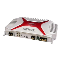
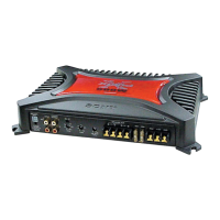
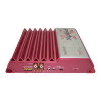
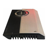
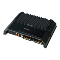
Outlines core technical details, connectivity, power, physical attributes, and included items.

Performance Metrics

Details electrical performance metrics like output power, frequency range, distortion, and operational parameters.

Protector Operation Tests

Thermal Protection Circuit Check

Procedure to verify the thermal protection circuit functionality.

Over Current Protection Circuit Check

Steps to test the over-current protection mechanism.

Offset Protection Circuit Check

Procedure to check the offset protection circuit.

Chassis Short Protection Circuit Check

Steps to verify chassis short circuit protection.

General Installation & Precautions

Wiring Connections Guide

Guide for connecting the amplifier to the car's power and speaker system.

Connection Guides

Input Connection Methods

Illustrates various high-level and line-level input connection methods.

Speaker Output Configurations

Details connection methods for 2-speaker, 1-speaker, subwoofer, and bridged systems.

Circuit Diagrams

Electronic Schematics

Detailed Amplifier Schematic

Comprehensive electronic schematic detailing all circuit components and connections.

Resistor Component List

Related product manuals