Do you have a question about the Sony XM-440EX and is the answer not in the manual?
Details the power output and total harmonic distortion for the amplifier.
Lists the key capabilities and design aspects of the amplifier.
Identifies and explains the purpose of each control and indicator on the amplifier.
Provides guidance on selecting a suitable location and preparing for mounting the amplifier.
Outlines critical safety measures and installation guidelines to prevent damage or hazards.
Details how to properly connect the power supply and speaker cords to the amplifier.
Details various methods for connecting audio input signals to the amplifier.
Guides on connecting different speaker system configurations to the amplifier.
Step-by-step procedure for removing the main circuit board from the amplifier.
Illustrates the overall functional blocks and signal flow within the amplifier circuit.
Visual representation of the component placement on the main and LED boards.
Detailed circuit diagram for the first half of the main amplifier board.
Detailed circuit diagram for the second half of the main amplifier board.
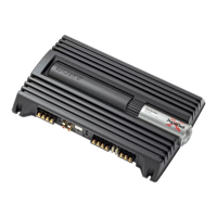
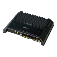
Visual guide to the physical layout and identification of amplifier components.
Lists main components like resistors, semiconductors, capacitors, coils, and connectors.
Continues listing capacitors, connectors, and diodes used in the amplifier.
Lists fuses, integrated circuits (ICs), jacks, and transistors used in the amplifier.
Continues listing transistors and resistors used in the amplifier circuit.
Continues the list of resistors used in the amplifier circuit, with part numbers and specifications.
Lists thermistors, miscellaneous components, accessories, and hardware like screws.
| Channels | 4 |
|---|---|
| Power at 4 Ohms | 40W x 4 |
| Frequency Response | 10Hz - 50kHz |
| Signal-to-Noise Ratio | 100 dB |
| Input Sensitivity | 0.2-4V |
| Crossover Frequency | 50 Hz - 300 Hz |