1
SERVICE MANUAL
AEP Model
UK Model
E Model
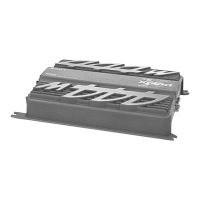
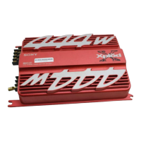
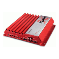
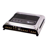
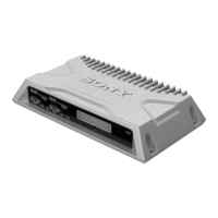
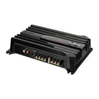
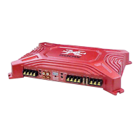
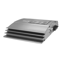
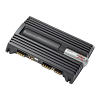
XM-444
STEREO POWER AMPLIFIER
Circuit system OTL (output transformerless) circuit Pulse
power supply
Inputs RCA pin jacks
High level input connector
Input level adjustment range
0.3 – 6 V (RCA pin jacks),
0.6 – 12 V (High level input)
Outputs Speaker terminals
Speaker impedance 2 – 8 Ω (stereo)
4 – 8 Ω (when used as a bridging amplifier)
Maximum outputs
4 Speakers: 80 W × 4 (at 4 Ω)
3 Speakers: 80 W × 2 + 222 W × 1 (at 4 Ω)
2 Speakers: 222 W × 2 (at 4 Ω)
Rated outputs (supply voltage at 14.4 V)
4 Speakers: 35 W × 4 (20 Hz – 20 kHz, 0.04% THD, at 4 Ω)
40 W × 4 (20 Hz – 20 kHz, 0.1% THD, at 2 Ω)
2 Speakers: 80 W × 2 (20 Hz – 20 kHz, 0.1% THD, at 4 Ω)
Frequency response 5 Hz – 80 kHz ( dB)
Harmonic distortion 0.005% or less (at 1 kHz, 4 Ω, 10 W)
Low-pass filter 80 Hz, –18 dB/oct
High-pass filter 80 Hz, –12 dB/oct
Power requirements 12 V DC car battery
(negative ground)
Power supply voltage 10.5 – 16 V
Current drain at rated output : 20 A (4 Ω, 35 W × 4)
Remote input : 1.5 mA
Dimensions Approx. 260 × 55 × 180 mm (w/h/d) not incl.
projecting parts and controls
Mass Approx. 2.4 kg not incl. accessories
Supplied accessories Mounting screws (4)
High level input cord (1)
Protection cap (1)
Design and specifications are subject to change without
notice.
SPECIFICATIONS
+0
–3
Ver 1.0 2002. 02
9-873-560-01
2002B0400-1
© 2002. 02
Sony Corporation
e Vehicle Company
Published by Sony Engineering Corporation