Do you have a question about the Sony XR-3758 and is the answer not in the manual?
Guidelines for repairing flexible circuit boards, including temperature control.
Advice on replacing chip components and handling tantalum capacitors.
Exploded view of the chassis assembly components.
Exploded view of the front panel assembly components.
Exploded view of the mechanism deck section 1 components.
Exploded view of the mechanism deck section 2 components.
Printed wiring layout for the main circuit board.
Electrical schematic for the main circuit board.
Printed wiring layout for the key control section.
Electrical schematic for the key control section.
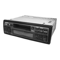
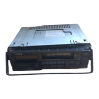
The Sony XR-3758/3759 is a car stereo system designed to provide FM/MW/LW radio reception and cassette playback capabilities. This service manual details the internal components, diagrams, and repair procedures for the UK model, with specific notes indicating similarities and differences between the XR-3758, XR-3759, and the XR-3750 UK model.
The device serves as an in-car entertainment system, offering a combination of radio and cassette playback. The radio tuner supports FM, MW (Medium Wave), and LW (Long Wave) bands, allowing users to access a wide range of broadcasts. The integrated cassette player enables the playback of audio cassettes, a common media format at the time of its manufacture. The system is designed for easy integration into a vehicle's dashboard, featuring a front panel with various control buttons and an LCD display for user interaction.
While detailed electrical specifications like power output or frequency response are not explicitly listed in the provided pages, the manual does offer insights into key components and their types.
The front panel design suggests user-friendly controls.
The service manual provides crucial information for technicians.
Overall, the Sony XR-3758/3759 is a robust car stereo system, and its service manual is a thorough guide for understanding, maintaining, and repairing the device.
| Brand | Sony |
|---|---|
| Model | XR-3758 |
| Category | Car Receiver |
| Language | English |