EasyManua.ls Logo

Sony XR-M500R Service Manual

Sony XR-M500R
66 pages
To Next Page IconTo Next Page
Page #1 background imageLoading...
Page #1 background image
SERVICE MANUAL
FM/AM (MW/LW) CASSETTE CAR STEREO
US Model
Canadian Model
XR-M550
AEP Model
UK Model
XR-M500R
SPECIFICATIONS
XR-M500R/M550
Photo: XR-M550
Model Name Using Similar Mechanism NEW
Tape Transport Mechanism Type MG-25E-136
Dolby noise reduction manufactured under license from
Dolby Laboratories Licensing Corporation.
“DOLBY” and the double-D symbol ; are trademarks
of Dolby Laboratories Licencing Corporation.
– Continued on next page –
Cassette player section
Other specifications
AUDIO POWER SPECIFICATIONS (US model)
POWER OUTPUT AND TOTAL HARMONIC DISTORTION
19 watts per channel minimum continuous average power into
4 ohms, 4 channels driven from 20 Hz to 20 kHz with no more
than 1% total harmonic distortion.
Tape track 4-track 2-channel stereo
Wow and flutter 0.08 % (WRMS)
Frequency response 30 – 20,000 Hz
Signal-to-noise ratio
Tuner section
FM
Tuning range 87.5 – 108.0 MHz (XR-M500R)
Antenna terminal External antenna connector
Intermediate frequency
10.7 MHz/450kHz
Usable sensitivity
8 dBf
Selectivity
75 dB at 400 kHz
Signal-to-noise ratio 66 dB (stereo),
72 dB (mono)
Harmonic distortion at 1 kHz
0.6 % (stereo),
0.3 % (mono)
Separation 35 dB at 1 kHz
Frequency response 30 – 15,000 Hz
MW/LW (XR-M500R)
Tuning range MW: 531 – 1,602 kHz
LW: 153 – 279 kHz
Aerial terminal External aerial connector
Intermediate frequency 10.7 MHz/450 kHz
Sensitivity MW: 30 µV
LW: 40 µV
AM (XR-M550)
Tuning range 530 – 1,710 kHz
Antenna terminal External antenna connector
Intermediate frequency 10.7 MHz/450 kHz
Sensitivity 30 µV
Dolby NR off
61 dB
58 dB
Dolby B NR
67 dB
64 dB
Cassette type
TYPE II,
TYPE I
IV
87.5 – 107.9 MHz (XR-M550)

Other manuals for Sony XR-M500R

Question and Answer IconNeed help?

Do you have a question about the Sony XR-M500R and is the answer not in the manual?

Sony XR-M500R Specifications

General IconGeneral
TypeCar Receiver
BrandSony
ModelXR-M500R
Built-in AmplifierYes
CD PlayerYes
MP3 PlaybackYes
WMA PlaybackYes
Radio TunerYes
FM Presets18
MW Presets6
Display TypeLCD
Remote ControlYes
Channels4.0 channels
Max Power Output52W x 4

Summary

Specifications

Audio Power Specifications

Details US model audio power output and total harmonic distortion.

Cassette Player Specifications

Covers tape track, wow/flutter, frequency response, and SNR.

Tuner Specifications

Details FM/AM tuning ranges, sensitivity, selectivity, and SNR.

Servicing Notes

Front Panel Opening Precautions

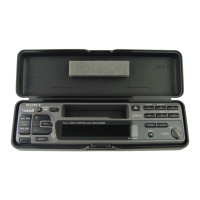
Instructions for safe opening of the front panel during service.

Model Identification

Identifies different main board types based on destination.

General Operation

Location of Controls (XR-M500R)

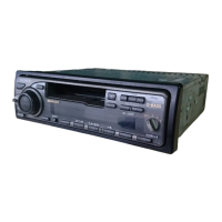
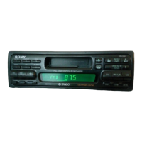
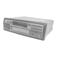
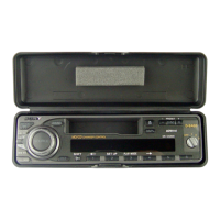
Identifies and explains the buttons and controls on the XR-M500R unit.

Setting the Clock

Step-by-step guide to setting the 24-hour digital clock.

Sound and Display Settings

Explains how to adjust settings like sound, display, language, and dimmer.

Installation Guide

Installation Precautions

Important considerations before and during unit installation.

Mounting Angle Adjustment

Guidance on adjusting the mounting angle for optimal fit.

Dashboard Installation Example

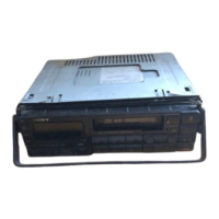
Illustrates the process of installing the unit in a dashboard.

Reset Button Operation

Instructions on how to press the reset button after installation.

Connections

Connection Cautions

Critical warnings regarding power, ground, and wiring for safe connection.

ACC Power Connection Warning

Specific warning for cars without ACC position on ignition switch.

Connection Example Notes

Important notes regarding control leads, memory hold, and speaker connections.

Power Connection Diagrams

Auxiliary Power Connector Variations

Illustrates different types of auxiliary power connectors and wiring.

Disassembly Procedure

Mechanism Deck Disassembly

Step-by-step guide to disassembling the mechanism deck (MG-25E-136).

Assembly Procedure

Front Panel Machinery Assembly

Details the assembly of front panel machinery, including motor block and cam.

Adjustments

Mechanical Adjustments

Procedures for mechanical adjustments like torque and tension.

Electrical Adjustments: Test Mode Operation

Procedure for entering and exiting the electrical test mode.

Electrical Adjustments: Tape Deck Speed

Steps for adjusting tape speed using a speed checker or frequency counter.

Dolby Level Adjustment

Procedure for adjusting Dolby level for optimal audio performance.

Diagrams and Schematics

Block Diagram - Tuner/Tape Section

Shows the functional blocks of the tuner and tape sections.

Block Diagram - Main Section

Illustrates the primary functional blocks of the main unit.

Block Diagram - Display/Bus Control

Details the display and bus control system architecture.

Block Diagram - Power Supply

Outlines the power supply circuitry and voltage distribution.

Printed Wiring Board - Main Board (Component Side)

Shows component layout on the main board's component side.

Exploded Views

Sub Panel Section Exploded View

Illustrates the parts and assembly of the sub panel.

Electrical Parts List

Display Components Listing

Lists part numbers and descriptions for display-related components.

Related product manuals