EasyManua.ls Logo

Sony XR-3750 Service Manual

Sony XR-3750
40 pages
To Next Page IconTo Next Page
Page #1 background imageLoading...
Page #1 background image
MICROFILM
XR-3750/C350
AEP Model
UK Model
SERVICE MANUAL
FM/MW/LW CASSETTE CAR STEREO
SPECIFICATIONS
Model Name Using Similar Mechanism NEW
Tape Transport Mechanism Type
MG-52A-135
Refer to RM-X2S/X3S SERVICE MANUAL (9-960-039-āˆ)
issued previously for information of remote commander
(RM-X2S) supplied with XR-C350.
Photo: XR-C350

Other manuals for Sony XR-3750

Question and Answer IconNeed help?

Do you have a question about the Sony XR-3750 and is the answer not in the manual?

Sony XR-3750 Specifications

General IconGeneral
Tuner BandsAM / FM
USB InputYes
BluetoothYes
Apple CarPlayYes
Android AutoYes
SiriusXMNo

Summary

SECTION 1 GENERAL

Location of Controls (XR-3750)

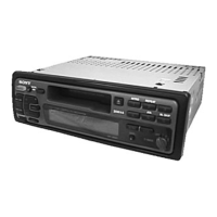
Details the front panel controls for the XR-3750 model.

Location of Controls (XR-C350)

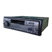
Details the front panel controls for the XR-C350 model.

Installation

Installation Precautions

Important safety and installation considerations for mounting the unit.

Mounting Angle Adjustment

Specifies the acceptable angle for unit installation.

Front Panel Detach and Attach

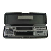
Instructions for removing and installing the front panel.

Mounting Examples

Illustrates typical installation scenarios in a dashboard.

Installation Connection Notes

Advice on connecting the unit, including grounding and noise reduction.

Connections

General Connection Precautions

Safety guidelines for wiring and power supply connections.

Ignition Key Switch Power Connection

How to connect the unit when the car lacks an accessory power position.

Reset Button Usage

Instructions for using the reset button after installation.

Control Function and Memory Connection

Explains pin functions and memory power supply.

Speaker Connection Notes

Guidelines for connecting speakers to prevent damage.

Power Connection Details

Power Connector Types and Wiring

Details on matching car power connectors and wiring harness.

Aerial Connection Example

How to connect the car's aerial using an adapter if needed.

Connection Diagrams

XR-3750 Connection Diagram

Illustrates wiring for the XR-3750 model.

XR-C350 Connection Diagram Example 1

Shows a basic connection setup for the XR-C350.

XR-C350 Connection Diagram Example 2

Shows an advanced connection setup for the XR-C350.

SECTION 2 DISASSEMBLY

Front Panel Assembly Disassembly

Steps to remove the front panel assembly.

Cover Assembly Disassembly

Instructions for removing the cover assembly.

Mechanism Deck Disassembly

Sub Panel and Mechanism Deck Removal

Steps to remove the sub panel and mechanism deck.

Main Board and Heat Sink Removal

Instructions for removing the main board and heat sink.

SECTION 3 ASSEMBLY OF MECHANISM DECK

Front Switch Alignment

How to align the front switch mechanism.

Gear Assembly Alignment

Steps for aligning gears during mechanism assembly.

Mechanism Deck Assembly (Chassis)

Chassis Assembly

How to assemble the chassis components.

Lever (Mode) Assembly

Instructions for fitting and installing the mode lever.

Mechanism Deck Assembly (Head Plate)

Lever (Pinch Selection) Assembly

Steps for assembling the pinch selection lever.

Head Plate Assembly

Instructions for assembling the head plate sub-assembly.

Mechanism Deck Assembly (Lever/Housing)

Lever (Pinch) Assembly

How to fit the pinch lever shaft and install the assembly.

Housing Assembly

Steps for assembling the housing components and hangers.

Mechanism Deck Assembly (Arm/Lever)

Arm (Suction) Assembly

Instructions for fitting the suction arm onto the shaft.

Lever (LDG-A/LDG-B) Assembly

Steps for fitting levers onto shafts and installing them.

Mechanism Deck Assembly (Gear/Guide)

Gear Assembly (LDG-FT)

How to assemble gears and levers for the LDG-FT mechanism.

Guide Assembly (C)

Steps for assembling the guide component.

SECTION 4 MECHANICAL ADJUSTMENTS

Torque Measurement

Specifications and procedures for torque measurements.

Tape Tension Measurement

Specifications for tape tension measurements.

SECTION 5 ELECTRICAL ADJUSTMENTS

Test Mode Function

How to enter and exit the test mode for adjustments.

Tape Deck Adjustments

Tape Speed Adjustment

Procedure for adjusting tape speed using a speed checker or counter.

Tuner Adjustments

FM Auto Scan/Stop Level Adjustment

How to adjust FM auto scan/stop levels.

Tuner Performance Adjustments

FM Stereo Separation Adjustment

Procedure to adjust FM stereo separation.

AM (MW) Auto Scan/Stop Level Adjustment

How to adjust AM/MW auto scan/stop levels.

Adjustment Location Guide

Adjustment Point Locations

Diagrams showing where to find adjustment points on the TU1 board.

SECTION 6 DIAGRAMS

IC Pin Function Description (Main Board)

Details pin functions for IC501 on the main board.

IC Pin Function Descriptions (Continued)

IC Pin Functions (System Control)

Lists pin functions for various ICs and components.

Printed Wiring Boards

Main Section - Board Layout

Shows the physical layout of components on the main board.

IC Block Diagrams

IC301 CXA2509AQ-T4 Block Diagram

Shows the internal block diagram of IC301.

IC401 LC75373ED Block Diagram

Shows the internal block diagram of IC401.

IC Block Diagrams (Continued)

IC601 BA3918-V2 Block Diagram

Shows the internal block diagram of IC601.

IC701 BA8270F-E2 Block Diagram

Shows the internal block diagram of IC701.

SECTION 7 EXPLODED VIEWS

Chassis Section Exploded View

Illustrates the exploded view of the chassis section.

Front Panel Section Exploded View

Front Panel Components

Lists and illustrates parts of the front panel section.

Mechanism Deck Section-1 Exploded View

Mechanism Deck Parts (MG-52A-135)

Details components of the mechanism deck section 1.

Mechanism Deck Section-2 Exploded View

Mechanism Deck Components (MG-52A-135)

Details components of the mechanism deck section 2.

SECTION 8 ELECTRICAL PARTS LIST

Connectors and Diodes

Lists part numbers for connectors, diodes, coils, and resistors.

Electrical Parts List (Switches)

Switch Components

Lists part numbers and descriptions for various switches.

Electrical Parts List (Capacitors)

Capacitor Components

Lists part numbers and specifications for capacitors.

Electrical Parts List (Capacitors/Connectors)

Capacitor and Connector Parts

Lists components from C271 to CN701.

Electrical Parts List (ICs and Transistors)

Integrated Circuits and Transistors

Lists part numbers for ICs and transistors.

Electrical Parts List (Resistors)

Resistor Components

Lists part numbers and values for resistors.

Electrical Parts List (Accessories)

Accessories and Packing Materials

Lists part numbers for accessories and hardware.

Installation Parts List

Parts for Installation and Connections

Lists parts needed for installation and connections.

Related product manuals