– 2 –
TABLE OF CONTENTS
1. GENERAL ................................................................... 3
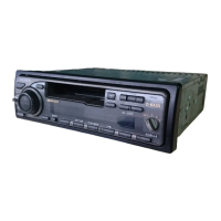
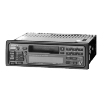
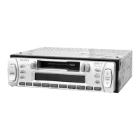
Location of Controls ........................................................ 3
Resetting the Unit ............................................................ 3
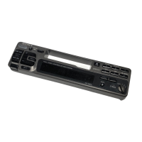
Detaching the Front Panel ............................................... 3
Preparing the Rotary Remote .......................................... 3
Setting the Clock ............................................................. 4
Using the Rotary Remote ................................................ 4
Adjusting the Sound Characteristics ............................... 5
Muting the Sound ............................................................ 5
Changing the Sound and Beep Tone................................ 5
Installation ....................................................................... 6
Connections ..................................................................... 7
2. DISASSEMBLY.......................................................... 10
3. ASSEMBLY OF MECHANISM DECK ........... 12
4. MECHANICAL ADJUSTMENTS ....................... 15
5. ELECTRICAL ADJUSTMENTS ...................... 15
6. DIAGRAMS
6-1. IC Pin Function Description ............................................ 16
6-2. Printed Wiring Board –MAIN Section– ......................... 20
6-3. Schematic Diagram –MAIN Section– ............................ 23
6-4. Printed Wiring Board –KEY Section– ........................... 27
6-5. Schematic Diagram –KEY Section– .............................. 29
7. EXPLODED VIEWS .......................................... 31
8. ELECTRICAL PARTS LIST ................................ 34
SERVICING NOTES
Flexible Circuit Board Repairing
• Keep the temperature of the soldering iron around 270 ˚C dur-
ing repairing.
• Do not touch the soldering iron on the same conductor of the
circuit board (within 3 times).
• Be careful not to apply force on the conductor when soldering
or unsoldering
Notes on chip component replacement
• Never reuse a disconnected chip component.
• Notice that the minus side of a tantalum capacitor may be dam-
aged by heat.