– 2 –
TABLE OF CONTENTS
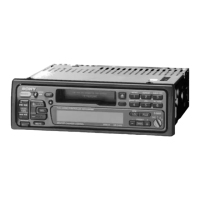
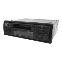
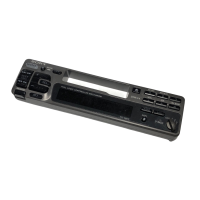
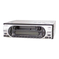
1. GENERAL
Location of Controls .......................................................... 3
Setting the Clock ............................................................... 4
Using the Rotary Remote .................................................. 4
Adjusting the Sound Characteristics ................................. 5
Muting the Sound .............................................................. 5
Changing the Sound and Beep Tone.................................. 5
Installation ......................................................................... 6
Connections ....................................................................... 7
2. DISASSEMBLY............................................................ 10
3. ASSEMBLY OF MECHANISM DECK ............. 12
4. MECHANICAL ADJUSTMENTS ......................... 15
5. ELECTRICAL ADJUSTMENTS
Test Mode .......................................................................... 15
Tape Deck Section ............................................................. 15
Tuner Section..................................................................... 16
6. DIAGRAMS
6-1. Printed Wiring Boards – Main Section – .......................... 22
6-2. Schematic Diagram – Main Section – ............................... 25
6-3. Printed Wiring Board – Display Section – ....................... 30
6-4. Schematic Diagram – Display Section – .......................... 32
6-5. IC Pin Function Description .............................................. 35
7. EXPLODED VIEWS .................................................. 37
8. ELECTRICAL PARTS LIST .................................. 40
SERVICING NOTES
Flexible Circuit Board Repairing
• Keep the temperature of the soldering iron around 270 ˚C during
repairing.
• Do not touch the soldering iron on the same conductor of the
circuit board (within 3 times).
• Be careful not to apply force on the conductor when soldering or
unsoldering .
Notes on chip component replacement
• Never reuse a disconnected chip component.
• Notice that the minus side of a tantalum capacitor may be dam-
aged by heat.
w
w
w
.
x
i
a
o
y
u
1
6
3
.
c
o
m
Q
Q
3
7
6
3
1
5
1
5
0
9
9
2
8
9
4
2
9
8
T
E
L
1
3
9
4
2
2
9
6
5
1
3
9
9
2
8
9
4
2
9
8
0
5
1
5
1
3
6
7
3
Q
Q
TEL 13942296513 QQ 376315150 892498299
TEL 13942296513 QQ 376315150 892498299
http://www.xiaoyu163.com
http://www.xiaoyu163.com
 Loading...