XR-CA300/CA320/CA320X
8
SECTION 2
DISASSEMBLY
Note: Follow the disassembly procedure in the numerical order given.
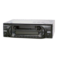
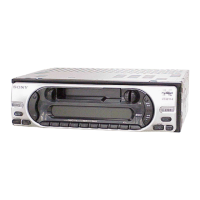
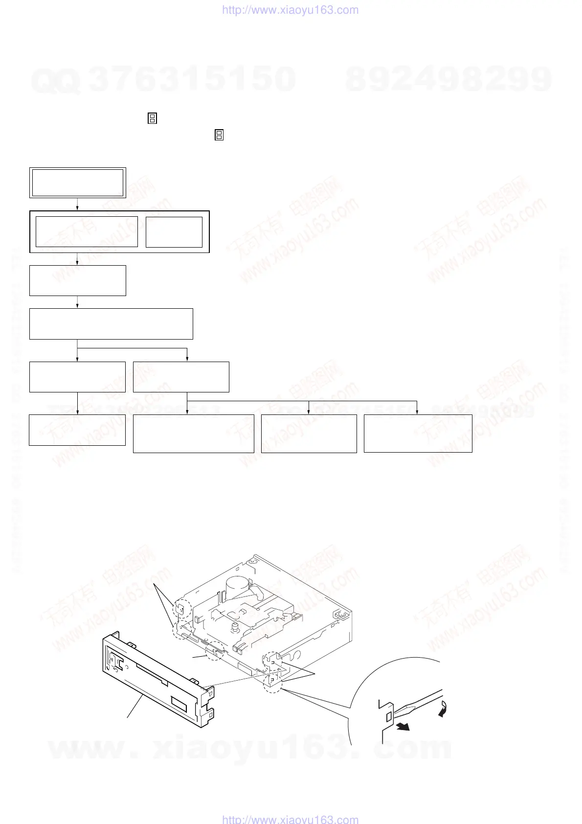
2-2. SUB PANEL
1
two claws
1
claw
1
two claws
2
sub panel
• This set can be disassembled in the order shown below.
2-1. DISASSEMBLY FLOW
Note 1: The process described in can be performed in any order.
Note 2: Without completing the process described in , the next process can not be performed.
Note 3: Illustration of disassembly is omitted.
SET
2-2. SUB PANEL
(Page 8)
FRONT PANEL SECTION
(Note 3)
COVER
(Note 3)
2-3. MECHANISM DECK (MG-36SZ11-32)
(Page 9)
2-4. MAIN BOARD
(Page 9)
2-5. HEAT SINK
(Page 10)
2-6. BRACKET (MD)
(Page 10)
2-7. MOTOR
(CAPSTAN/REEL) (M901)
(Page 11)
2-8. MAIN BELT,
SUB BELT (C)
(Page 11)
2-9. HEAD
(PLAY BACK) (HP901)
(Page 12)
w
w
w
.
x
i
a
o
y
u
1
6
3
.
c
o
m
Q
Q
3
7
6
3
1
5
1
5
0
9
9
2
8
9
4
2
9
8
T
E
L
1
3
9
4
2
2
9
6
5
1
3
9
9
2
8
9
4
2
9
8
0
5
1
5
1
3
6
7
3
Q
Q
TEL 13942296513 QQ 376315150 892498299
TEL 13942296513 QQ 376315150 892498299
http://www.xiaoyu163.com
http://www.xiaoyu163.com
 Loading...