Do you have a question about the Sony XR-C650RDS and is the answer not in the manual?
Details the performance characteristics of the cassette player section, including wow/flutter and frequency response.
Outlines the tuning range, sensitivity, selectivity, and signal-to-noise ratio for FM and MW/LW bands.
Lists the speaker output impedance and maximum power output for the power amplifier section.
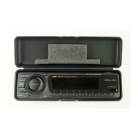
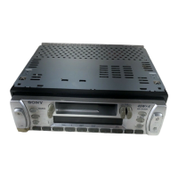
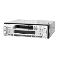
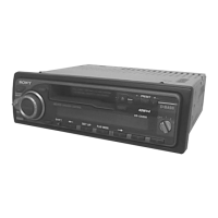
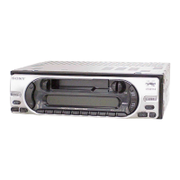
Identifies the location and function of all buttons and controls on the unit.
Provides instructions for setting the 24-hour digital clock display.
Explains how to skip tracks, repeat playback, and use various tape modes like Intro and B.Skip.
Details automatic and manual methods for storing radio stations into memory.
Offers guidance on tuning presets, improving FM stereo reception, and using local link functions.
Explains Radio Data System features like station name display and automatic retuning.
Describes how to listen to traffic and emergency announcements automatically.
Instructions for finding radio stations based on programme type selection.
Explains automatic clock setting using RDS transmission data.
Details how to operate the unit using the supplied rotary remote control.
Covers adjusting bass, treble, balance, fader, and muting the audio output.
Explains how to customize sound settings and display options for CD/MD.
Covers playing CDs/MDs, auto scrolling disc names, and displaying recording dates.
Instructions for locating specific tracks, points in tracks, and discs by number.
Details scan, repeat, and random shuffle play modes for CD/MD playback.
Guides on creating, playing, and erasing custom track programmes for CD changers.
Explains how to label CDs, display disc memos, and locate discs by name.
Illustrates various connection examples for speakers, amplifiers, and other accessories.
Step-by-step instructions for removing the unit's cover and front panel.
Details on disassembling the sub panel and the main mechanism deck block.
Guides on removing the heat sink and the main circuit board.
Instructions for aligning the rotary switch and gears during mechanism reassembly.
Procedures for assembling the chassis and various levers like the mode lever.
Details on assembling the head plate and pinch selection levers.
Steps for assembling the housing and pinch levers with springs and washers.
Instructions for assembling the suction arm and LDG-A/LDG-B levers.
Covers the assembly of the FT gear, tension spring, and guide components.
Details on measuring torque and tape tension, requiring specific tools.
Covers deck section, tape speed, and DOLBY level adjustments using test tapes.
Procedures for test mode setup and FM auto scan/stop level calibration.
Covers stereo separation, noise focus, RDS S-meter, and FM adjustments.
Instructions for calibrating the MW auto scan and stop level settings.
Lists pin assignments and functions for key integrated circuits in the tuner control.
Illustrates signal paths and functional blocks of the TC section.
Component layout and trace diagrams for the Main Section's printed wiring boards.
Shows signal paths and functional blocks of the Main section.
Detailed circuit schematics for the Main Section of the unit.
Component layout and trace diagrams for the Panel Section's printed wiring boards.
Detailed circuit schematics for the Panel Section of the unit.
Visual representations of the internal circuitry of various integrated circuits.
Lists switches, diodes, ICs, display panel, and other components for the key board.
Enumerates various capacitors and connectors found on page 57.
Lists semiconductor components including diodes, transistors, and resistors from page 58.
Lists additional transistors, resistors, switches, and tuner components from page 59.
Lists further resistors, transistors, and switches from page 60.
Lists more resistors, switches, and connectors from page 61.
Lists the remaining capacitors and diodes from page 62.
Lists screws, brackets, frames, and other parts for installation and connection from page 68.
| RDS | Yes |
|---|---|
| CD Playback | Yes |
| USB Port | No |
| Bluetooth | No |
| Changer Control | Yes |
| Display Type | LCD |
| Detachable Face | Yes |
| Channels | 4 |
| Built-in Display | Yes |
| AUX Input | No |
| MP3 Playback | No |
| WMA Playback | No |
| Radio Tuner | Yes |
| Equalizer | Yes |
| Tuner Bands | FM |
| Power Output | 4 x 45 Watts |
| Dimensions (W x H x D) | 178 x 50 mm |