EasyManua.ls Logo

Sony ZS-S50CP Service Manual

Sony ZS-S50CP
60 pages
To Next Page IconTo Next Page
Page #1 background imageLoading...
Page #1 background image
SERVICE MANUAL
PERSONAL AUDIO SYSTEM
SPECIFICATIONS
Ver. 1.1 2007.08
9-887-662-02
2007H05-1
© 2007.08
Sony Corporation
Personal Audio Division
Published by Sony Techno Create Corporation
Model Name Using Similar Optical Pick-up Block NEW
Optical Pick-up Block Type KSM-213CCP
ZS-S50CP
AEP Model
E Model
CD player section
System
Compact disc digital audio system
Laser diode properties
Emission duration: Continuous
Laser output: Less than 44.6 µW
(This output is the value measured at a distance of about 200 mm from
the objective lens surface on the optical pick-up block with 7 mm
aperture.)
Number of channels
2
Frequency response
20 - 20 000 Hz +1/1 dB
Wow and flutter
Below measurable limit
Radio section
Frequency range
FM: 87.5 - 108 MHz
AM:
except Mexican model:
531 - 1 611 kHz (9 kHz step)
530 - 1 610 kHz (10 kHz step)
Mexican model:
530 - 1 710 kHz
IF
FM: 10.7 MHz
AM: 450 kHz
Antennas
FM: Telescopic antenna
AM: Built-in ferrite bar antenna
General
Speaker
Full range: 10 cm dia., 6 , cone type (2)
Input
AUDIO IN jack (stereo minijack): Minimum input level 245 mV
Outputs
Headphones jack (stereo minijack)
For 16 - 64 impedance headphones
Power output
4.5 W + 4.5 W (at 6 , 10% harmonic distortion)
Power requirements
For player:
Mexican model: 120 V AC, 60 Hz
Singapore model: 230 - 240 V AC, 50 Hz
Other models: 230 V AC, 50 Hz
9 V DC, 6 R20 (size D) batteries
For remote control:
3 V DC, 2 R6 (size AA) batteries
Power consumption
AC 16 W
Battery life
For player:
FM Radio reception
Sony R20P: approx. 30 h
Sony alkaline LR20: approx. 60 h
CD playback
Sony R20P: approx. 8 h
Sony alkaline LR20: approx. 20 h
It is recommended that you use alkaline batteries.
Dimensions
Approx. 480 × 156 × 250 mm (w/h/d)
(incl. projecting parts)
Mass
Approx. 4.3 kg (incl. batteries)
Supplied accessories
AC power cord (1)
Remote control (1)
Design and specifications are subject to change without notice.

Other manuals for Sony ZS-S50CP

Question and Answer IconNeed help?

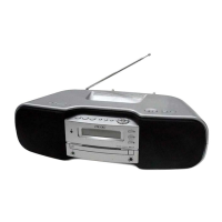
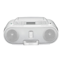
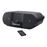
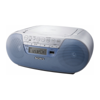
Do you have a question about the Sony ZS-S50CP and is the answer not in the manual?

Sony ZS-S50CP Specifications

General IconGeneral
BrandSony
ModelZS-S50CP
CategoryStereo System
LanguageEnglish

Summary

SPECIFICATIONS

SECTION 3 DISASSEMBLY

3-1. DISASSEMBLY FLOW

A chart outlining the sequence of disassembly for major components.

3-2. CABINET (Lower) Assy

Detailed procedure for removing the lower cabinet assembly.

3-3. Cabinet (Upper) Assy

Detailed procedure for removing the upper cabinet assembly.

3-4. CD Block

Steps to remove the CD block assembly.

3-5. Main Block Assy

Steps to remove the main block assembly.

3-6. Main Board, CD Block Assy

Procedure for removing the main and CD block assemblies together.

3-7. SPEAKER (10 cm) (SP101) (L-CH), SPEAKER (10 cm) (SP201) (R-CH)

Instructions for removing the left and right speaker units.

3-8. BELT

Procedure for accessing and replacing the belt.

3-9. OPTICAL PICK-UP BLOCK (KSM-213CCP)

Steps for removing the optical pick-up block.

SECTION 5 ELECTRICAL ADJUSTMENTS

SECTION 1 SERVICING NOTES

HANDLING THE OPTICAL PICK-UP BLOCK

Precautions for handling the optical pick-up block to prevent damage.

LASER DIODE EMISSION CHECK

Safety guidelines for checking the laser diode emission.

MODEL IDENTIFICATION

Information on identifying the model number label.

UNLEADED SOLDER

Notes on using unleaded solder, including its characteristics.

TUNER SECTION

SECTION 6 DIAGRAMS

6-1. BLOCK DIAGRAM - CD SERVO Section -

Functional block diagram of the CD servo control system.

6-2. BLOCK DIAGRAM - TUNER Section -

Functional block diagram of the radio tuner section.

6-3. BLOCK DIAGRAM - MAIN Section -

Functional block diagram of the main control system.

6-4. BLOCK DIAGRAM - POWER SUPPLY Section -

Functional block diagram of the power supply circuit.

6-6. SCHEMATIC DIAGRAM - CD Board -

Detailed circuit schematic for the CD board.

6-8. SCHEMATIC DIAGRAM - TU Board -

Detailed circuit schematic for the TU board.

6-11. SCHEMATIC DIAGRAM - MAIN Section (1/2) -

Detailed circuit schematic for the Main board, part 1 of 2.

6-12. SCHEMATIC DIAGRAM - MAIN Section (2/2) -

Detailed circuit schematic for the Main board, part 2 of 2.

Waveforms

Example waveforms for the CD, TU, Main, and LCD board signals.
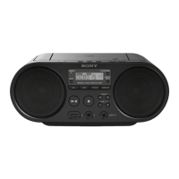
IC Block Diagrams

Main Board IC Descriptions

LCD Board IC Description

IC Pin Function Description

Main Board IC803 Pinout

SECTION 7 EXPLODED VIEWS

SECTION 8 ELECTRICAL PARTS LIST

Related product manuals